Search
PATENT PORTFOLIO
FACET: Future Air Traffic Management Concepts Evaluation Tool
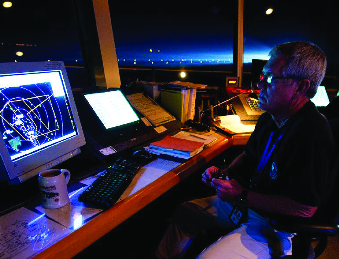
Actual air traffic data and weather information are utilized to evaluate an aircrafts flight-plan route and predict its trajectories for the climb, cruise, and descent phases. The dynamics for heading (the direction the aircraft nose is pointing) and airspeed are also modeled by the FACET software, while performance parameters, such as climb/descent rates and speeds and cruise speeds, can also be obtained from data tables. The resulting trajectories and traffic flow data are presented in a 3-D graphical user interface. The FACET software is modular and is written in the Java and C programming languages. Notable FACET applications include reroute conformance monitoring algorithms that have been implemented in one of the Federal Aviation Administrations nationally deployed, real-time operational systems.
Unmanned Aerial Systems (UAS) Traffic Management
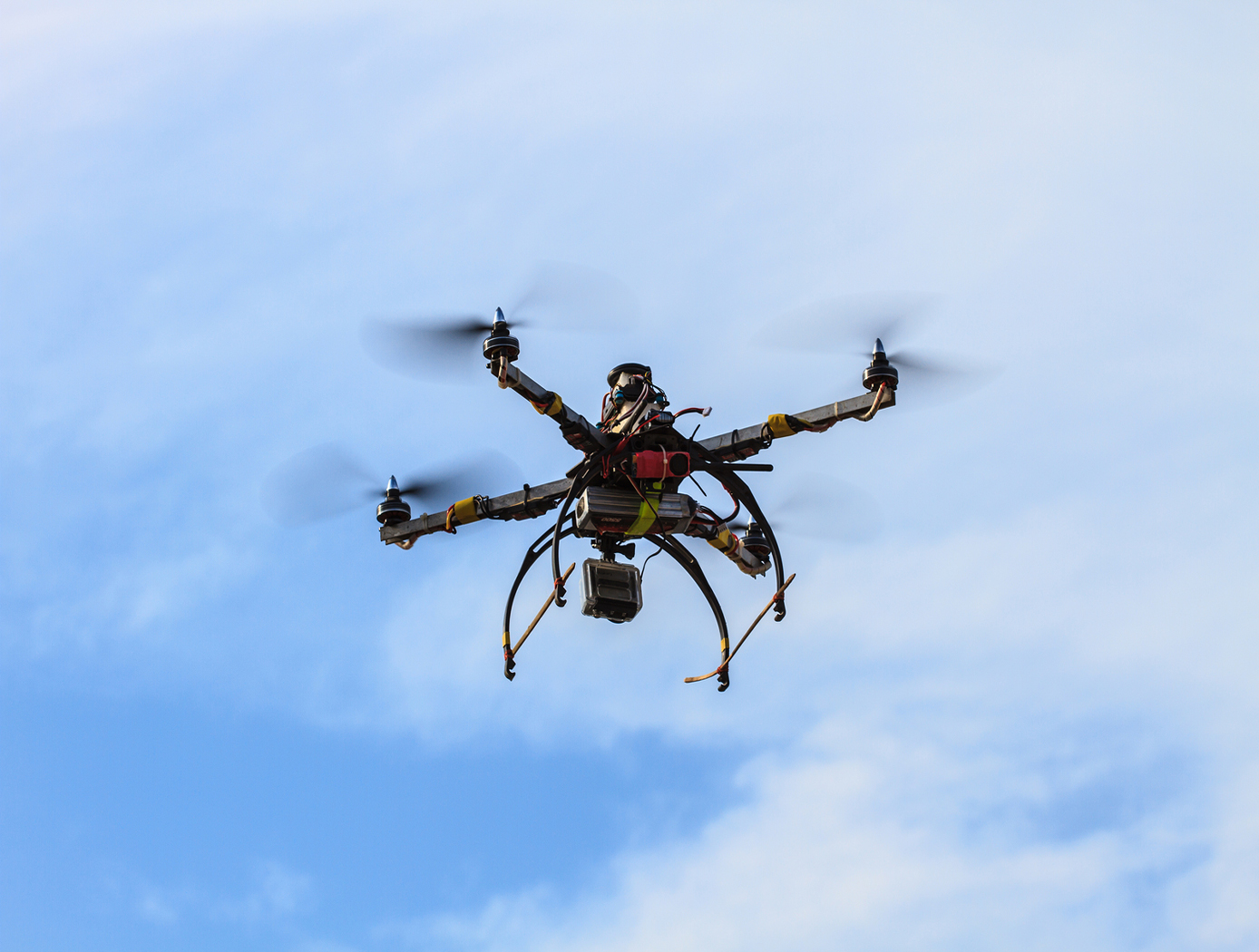
NASA Ames has developed an Autonomous Situational Awareness Platform system for a UAS (ASAP-U), a traffic management system to incorporate Unmanned Aerial Systems (UASs) into the National Airspace System. The Autonomous Situational Awareness Platform (ASAP) is a system that combines existing navigation technology (both aviation and maritime) with new procedures to safely integrate Unmanned Aerial Systems (UASs) with other airspace vehicles. It uses a module called ASAP-U, which includes a transmitter, receivers, and various links to other UAS systems. The module collects global positioning system GPS coordinates and time from a satellite antenna, and this data is fed to the UAS's flight management system for navigation. The ASAP-U module autonomously and continuously sends UAS information via a radio frequency (RF) antenna using Self-Organized Time Division Multiple Access (SOTDMA) to prevent signal overlap. It also receives ASAP data from other aircraft. In case of transmission overload, priority is given to closer aircraft. Additionally, the module can receive weather data, navigational aid data, terrain data, and updates to the UAS flight plan. The collected data is relayed to the flight management system, which includes various databases and a navigation computer to calculate necessary flight plan modifications based on regulations, right-of-way rules, terrain, and geofencing. Conflicts are checked against databases, and if none are found, the flight plan is implemented. If conflicts arise, modifications can be made. The ASAP-U module continuously receives and transmits data, including UAS data and data from other aircraft, to detect conflicts with other aircraft, terrain, weather, and geofencing. Based on this information, the flight management system determines the need for course adjustments and the flight control system executes them for a safe flight route.
Space Traffic Management (STM) Architecture
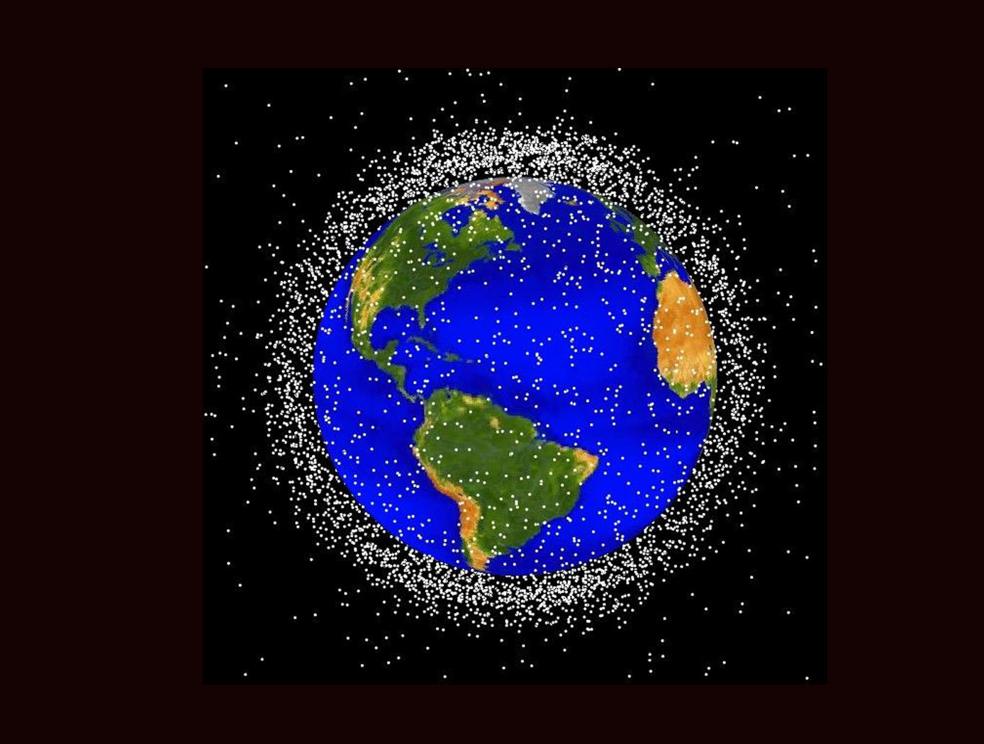
As ever larger numbers of spacecraft seek to make use of Earth's limited orbital volume in increasingly dense orbital regimes, greater coordination becomes necessary to ensure these spacecraft are able to operate safely while avoiding physical collisions, radio-frequency interference, and other hazards. While efforts to date have focused on improving Space Situational Awareness (SSA) and enabling operator to operator coordination, there is growing recognition that a broader system for Space Traffic Management (STM) is necessary. The STM architecture forms the framework for an STM ecosystem, which enables the addition of third parties that can identify and fill niches by providing new, useful services. By making the STM functions available as services, the architecture reduces the amount of expertise that must be available internally within a particular organization, thereby reducing the barriers to operating in space and providing participants with the information necessary to behave responsibly. Operational support for collision avoidance, separation, etc., is managed through a decentralized architecture, rather than via a single centralized government-administered system.
The STM system is based on the use of standardized Application Programming Interfaces (API) to allow easier interconnection and conceptual definition of roles to more easily allow suppliers with different capabilities to add value to the ecosystem. The architecture handles basic functions including registration, discovery, authentication of participants, and auditable tracking of data provenance and integrity. The technology is able to integrate data from multiple sources.
Computer Vision Lends Precision to Robotic Grappling
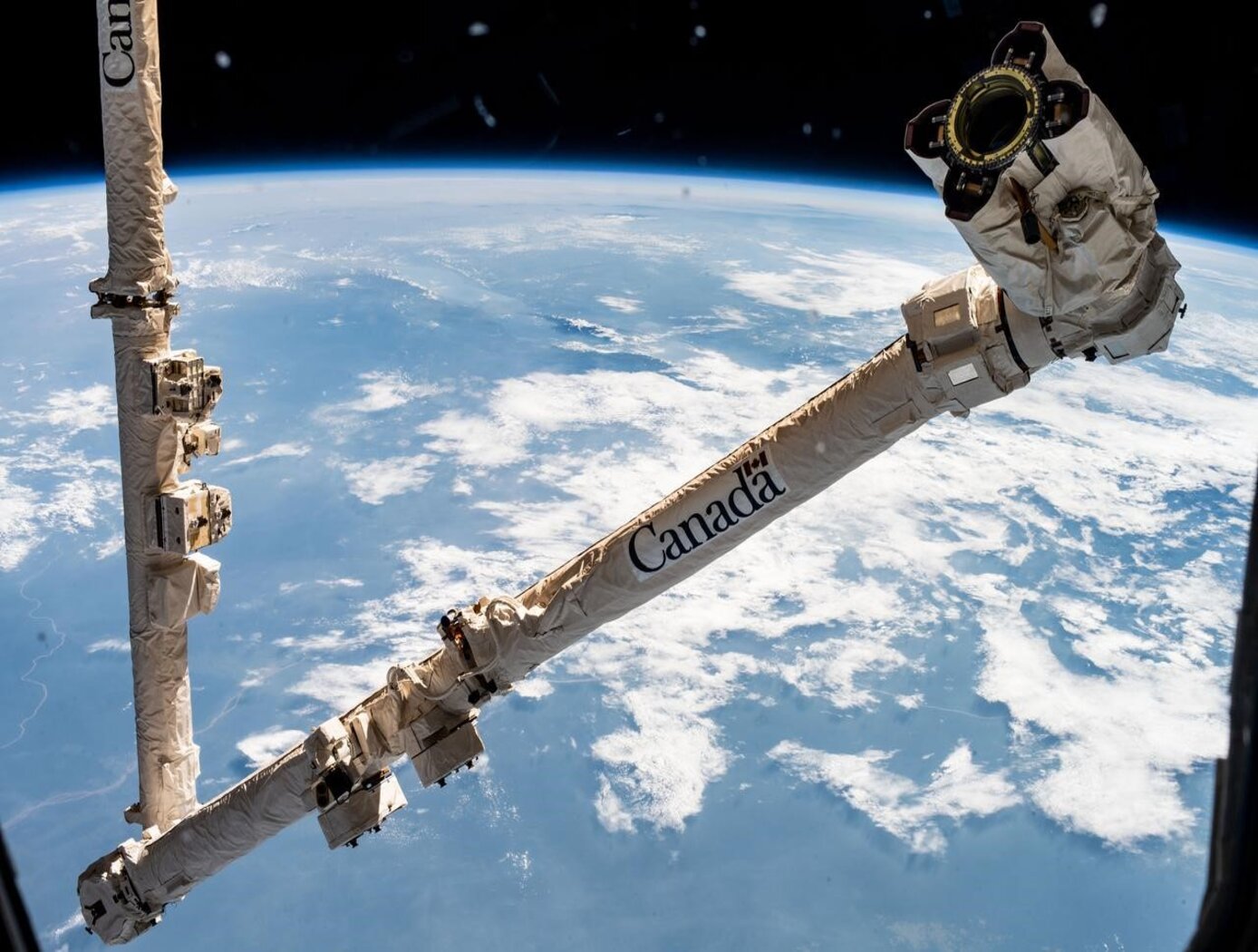
The goal of this computer vision software is to take the guesswork out of grapple operations aboard the ISS by providing a robotic arm operator with real-time pose estimation of the grapple fixtures relative to the robotic arm’s end effectors. To solve this Perspective-n-Point challenge, the software uses computer vision algorithms to determine alignment solutions between the position of the camera eyepoint with the position of the end effector – as the borescope camera sensors are typically located several centimeters from their respective end effector grasping mechanisms.
The software includes a machine learning component that uses a trained Region-based Convolutional Neural Network (R-CNN) to provide the capability to analyze a live camera feed to determine ISS fixture targets a robotic arm operator can interact with on orbit. This feature is intended to increase the grappling operational range of ISS’s main robotic arm from a previous maximum of 0.5 meters for certain target types, to greater than 1.5 meters, while significantly reducing computation times for grasping operations.
Industrial automation and robotics applications that rely on computer vision solutions may find value in this software’s capabilities. A wide range of emerging terrestrial robotic applications, outside of controlled environments, may also find value in the dynamic object recognition and state determination capabilities of this technology as successfully demonstrated by NASA on-orbit.
This computer vision software is at a technology readiness level (TRL) 6, (system/sub-system model or prototype demonstration in an operational environment.), and the software is now available to license. Please note that NASA does not manufacture products itself for commercial sale.

Selective Access and Editing in a Database
A complex project has many tasks and sub-tasks, many phases and many collaborators, and will often have an associated database with many users, each of which has a limited need to know that does not extend to all information in the database. This invention relates to selective access to simultaneous editing of different portions of a database. It provides selective access to as many as 2N-1 (or 2N) mutually exclusive portions of a database by different subgroups of N users. One or more members of an access subgroup can edit a document or other information collection, to which the members have access simultaneously. In this system the database receives information from one or more information sources and is queried by a plurality of users. The database permits selective access of a given user to different portions of the database, depending upon the users identity and access permissions. Optionally, members of the same access subgroup can be assigned different numerical priorities in a queue so that, as between first and second users in the subgroup, draft editing of a document by the first user will subsequently be reviewed, declined, or either partly entered or wholly entered by the second user. User access to different portions of the database is initially determined when a user account is set up. User access can be subsequently changed according to the circumstances.
Vision-based Approach and Landing System (VALS)
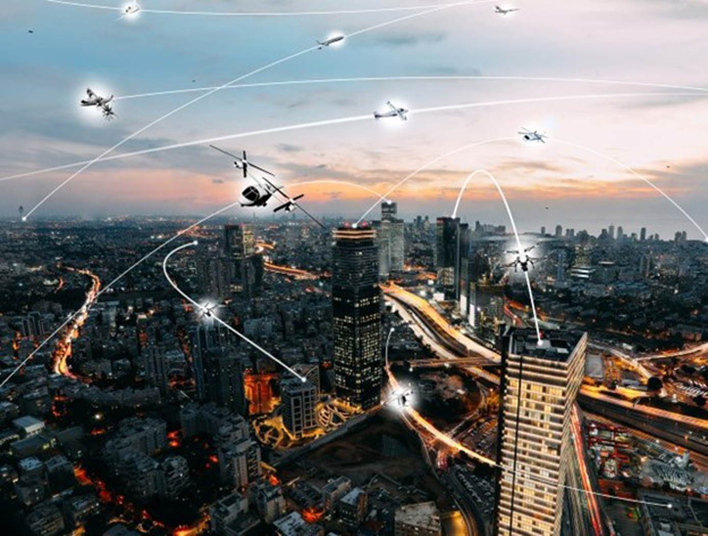
The novel Vision-based Approach and Landing System (VALS) provides Advanced Air Mobility (AAM) aircraft with an Alternative Position, Navigation, and Timing (APNT) solution for approach and landing without relying on GPS. VALS operates on multiple images obtained by the aircraft’s video camera as the aircraft performs its descent. In this system, a feature detection technique such as Hough circles and Harris corner detection is used to detect which portions of the image may have landmark features. These image areas are compared with a stored list of known landmarks to determine which features correspond to the known landmarks. The world coordinates of the best matched image landmarks are inputted into a Coplanar Pose from Orthography and Scaling with Iterations (COPOSIT) module to estimate the camera position relative to the landmark points, which yields an estimate of the position and orientation of the aircraft. The estimated aircraft position and orientation are fed into an extended Kalman filter to further refine the estimation of aircraft position, velocity, and orientation. Thus, the aircraft’s position, velocity, and orientation are determined without the use of GPS data or signals. Future work includes feeding the vision-based navigation data into the aircraft’s flight control system to facilitate aircraft landing.
Traffic Aware Strategic Aircrew Requests (TASAR)
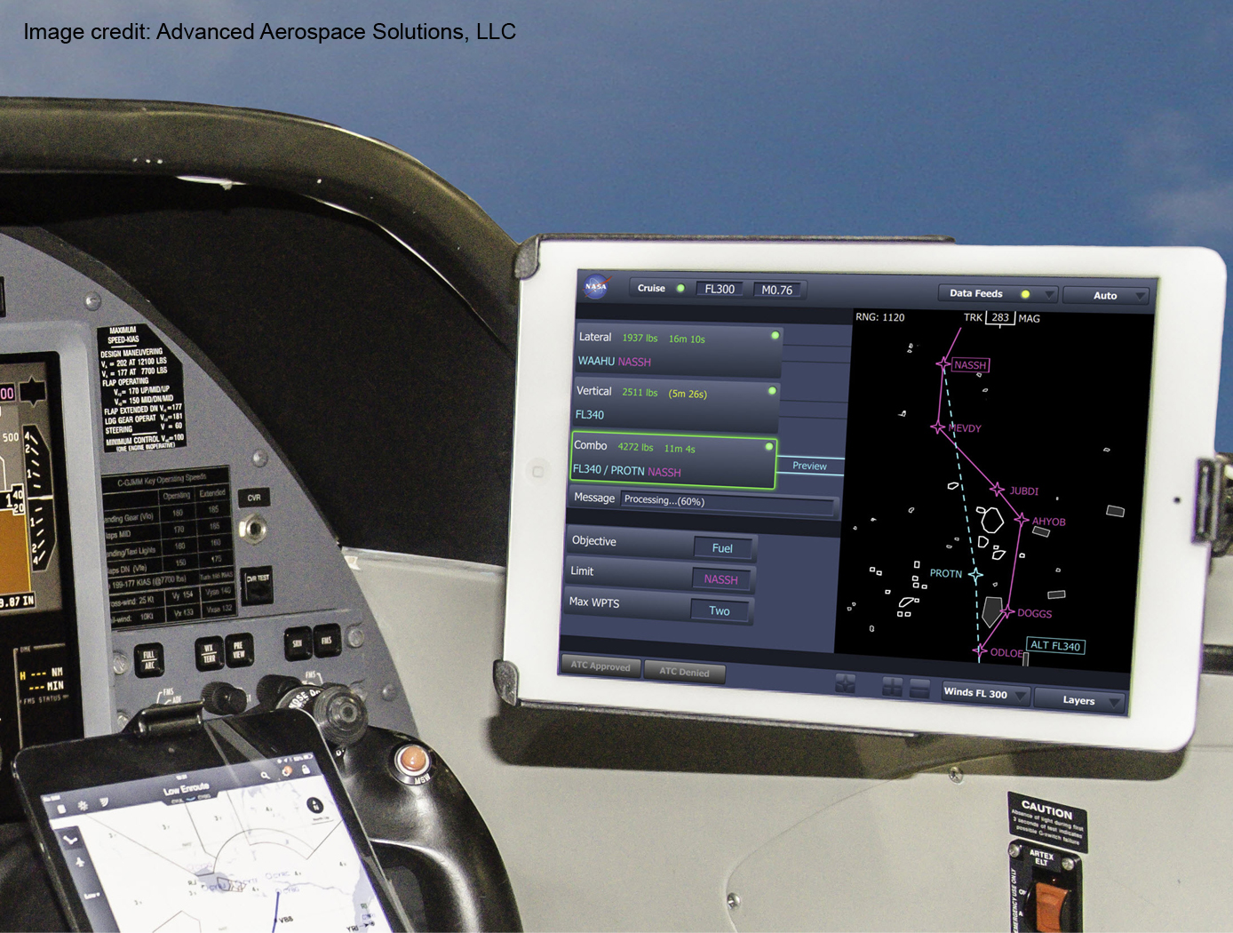
The NASA software application developed under the TASAR project is called the Traffic Aware Planner (TAP). TAP automatically monitors for flight optimization opportunities in the form of lateral and/or vertical trajectory changes. Surveillance data of nearby aircraft, using ADS-B IN technology, are processed to evaluate and avoid possible conflicts resulting from requested changes in the trajectory. TAP also leverages real-time connectivity to external information sources, if available, of operational data relating to winds, weather, restricted airspace, etc., to produce the most acceptable and beneficial trajectory-change solutions available at the time. The software application is designed for installation on low-cost Electronic Flight Bags that provide read-only access to avionics data. The user interface is also compatible with the popular iPad. FAA certification and operational approval requirements are expected to be minimal for this non-safety-critical flight-efficiency application, reducing implementation cost and accelerating adoption by the airspace user community.
Awarded "2016 NASA Software of the Year"
System for In-situ Defect Detection in Composites During Cure
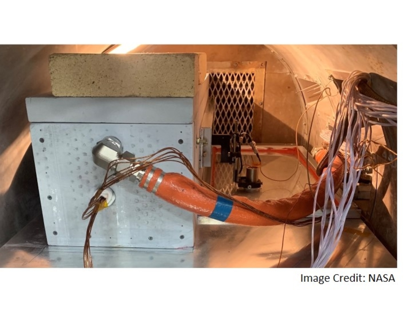
NASA's System for In-situ Defect (e.g., porosity, fiber waviness) Detection in Composites During Cure consists of an ultrasonic portable automated C-Scan system with an attached ultrasonic contact probe. This scanner is placed inside of an insulated vessel that protects the temperature-sensitive components of the scanner. A liquid nitrogen cooling systems keeps the interior of the vessel below 38°C. A motorized X-Y raster scanner is mounted inside an unsealed cooling container made of porous insulation boards with a cantilever scanning arm protruding out of the cooling container through a slot. The cooling container that houses the X-Y raster scanner is periodically cooled using a liquid nitrogen (LN2) delivery system. Flexible bellows in the slot opening of the box minimize heat transfer between the box and the external autoclave environment. The box and scanning arm are located on a precision cast tool plate. A thin layer of ultrasonic couplant is placed between the transducer and the tool plate. The composite parts are vacuum bagged on the other side of the tool plate and inspected. The scanning system inside of the vessel is connected to the controller outside of the autoclave. The system can provide A-scan, B-scan, and C-scan images of the composite panel at multiple times during the cure process.
The in-situ system provides higher resolution data to find, characterize, and track defects during cure better than other cure monitoring techniques. In addition, this system also shows the through-thickness location of any composite manufacturing defects during cure with real-time localization and tracking. This has been demonstrated for both intentionally introduced porosity (i.e., trapped during layup) as well processing induced porosity (e.g., resulting from uneven pressure distribution on a part). The technology can be used as a non-destructive evaluation system when making composite parts in in an oven or an autoclave, including thermosets, thermoplastics, composite laminates, high-temperature resins, and ceramics.
VTOL UAV With the Cruise Efficiency of a Conventional Fixed Wing UAV
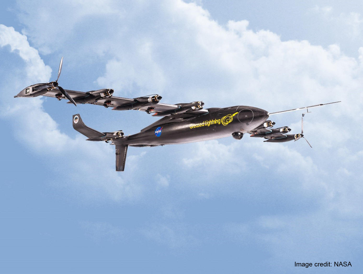
The core technology that enables the Greased Lightning UAV is the aerodynamic efficiency it achieves in its cruise configuration. Electric motors at each propeller negate the need for drive shafts and gearing which enables this Distributed Electric Propulsion (DEP) aircraft configuration. The design is intended to utilize a hybrid electric drive system that includes small diesel engines which drive alternators to power the electric motors and to charge an on-board battery system. The batteries provide the power boost needed for VTOL and hovering. Numerous other novel design elements are incorporated, such as folding propellers to minimize drag when not in operation, such that the propulsive efficiency can be nearly ideal at both hover and wing borne flight conditions.



