Search
Robotics Automation and Control

Assemblers
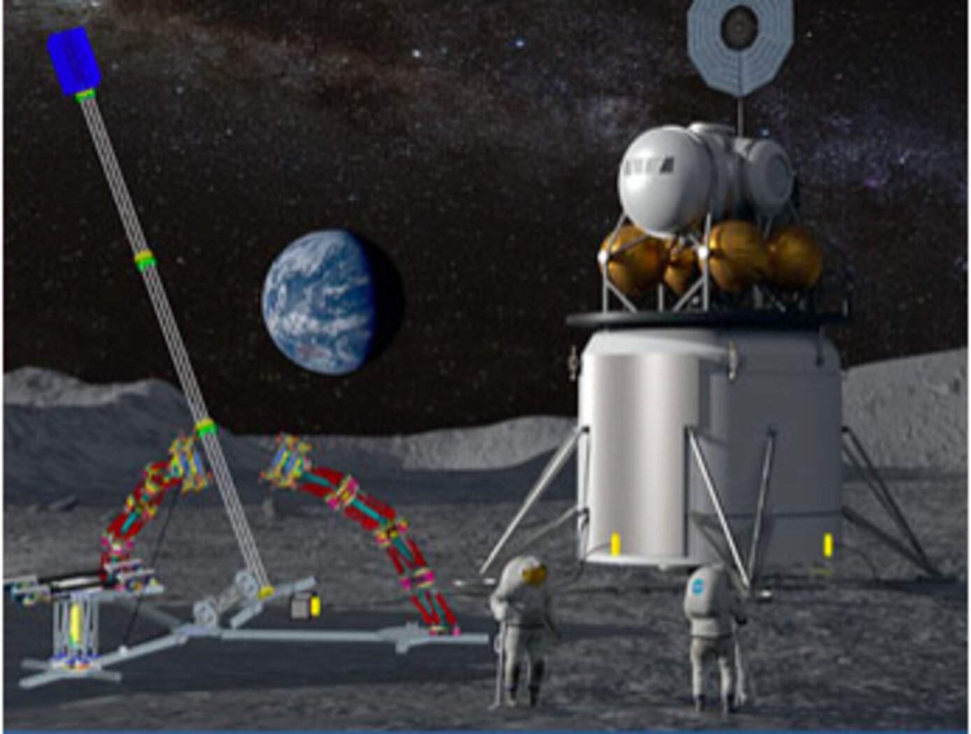
Assemblers are a team of modular robots that work together to build things. Each Assembler is a stack of one or more Stewart platforms, or hexapods, made up of two plates connected by six linear actuators for movement, enabling a full six-degree-of-freedom (DOF) pose of the top plate relative to the bottom plate (see figure to the right). An end effector on each Assembler enables gripping, lifting, and welding/joining. The Assemblers system architecture features novel control algorithms and software, sensors, and communicator technology that coordinate operations of Assembler teams. The control system includes an important module for task management that estimates how many robots are needed, the optimal number of hexapods in each Assembler, and the estimated voltage needed. There are also modules for trajectory generation, joint control, sensor fusion, and fault detection. The novel control system directs the Assembler operations for high accuracy and precision, yet there is built-in dynamic resilience to failure. For example, if a single hexapod on an Assembler fails, the system deems it “rigid” in its last pose and redistributes the work to the other Assemblers.
The image below shows a storyboard of operations for how Assemblers might build a solar array. NASA has developed a hardware demo with communications between subsystems, backed up by detailed simulations of the kinematics and actuator dynamics.
manufacturing

AERoBOND: Large-scale Composite Manufacturing
This technology (AERoBOND) enables the assembly of large-scale, complex composite structures while maintaining predictable mechanical and material properties. It does so by using a novel barrier-ply technology consisting of an epoxy resin/prepreg material with optimal efficiency, reliability, and performance. The barrier-ply materials prevent excessive mixing between conventional composite precursors and stoichiometrically-offset epoxy precursors during the cure process by forming a gel early in the cure cycle before extensive mixing can occur. The barrier ply is placed between the conventional laminate preform and the stoichiometrically-offset ply or plies placed on the preform surface, thus preventing excessive mass transfer between the three layers during the cure process. In practice, the barrier ply could be combined with the offset ply to be applied as a single, multifunctional surfacing layer enabling unitized assembly of large and complex structures. The AERoBOND method is up to 40% faster than state-of-the-art composite manufacturing methods, allows for large-scale processing of complex structures, eliminates the potential for weak bond failure modes, and produces composites with comparable mechanical properties as compared with those prepared by co-cure.
Robotics Automation and Control

Robotic system for assembly and maintenance of lightweight reconfigurable structures
To enable the goal of autonomous assembly of high performing structures, a robot system must be able to travel across a lattice structure in all dimensions, transport and align a unit cell module to the correct location and fasten the module to the existing structure. In this system, a team of multiple mobile bipedal robots work together to carry, transfer, and place 3D-lattice modules (e.g., cuboctahedron voxels) to form a 3D lattice structure. The team of mobile bipedal robots autonomously provide transportation, placement, unpacking, and assembly of voxel modules into functional structures and systems. As the team of mobile bipedal robots live and locomote on the 3D-lattice structure, they monitor health and performance, enabling repair and reconfiguration when needed. The mobile bipedal robots work together in different roles, for example, one as a cargo transport robot and the other as a crane robot. The cargo transport robot and the crane robot work together to move the voxels from one location to another. Each robot includes at least one electronic control module that receives commands from another robot or a central control system. A central control system implements a plan to control the motion sequences of the robots to maximize efficiency and to optimize the work required to completely assemble a structure. The plan is pre-computed or computed during implementation by the central control system or the robots themselves, according to algorithms that utilize the regularity of the lattice structure to simplify path planning, align robotic motions with minimal feedback, and minimize the number of the degrees of freedom required for the robots to locomote across and throughout the 3D-lattice structure and perform structural assembly.
Robotics Automation and Control

Single-Action-Lock Structural Space Joint
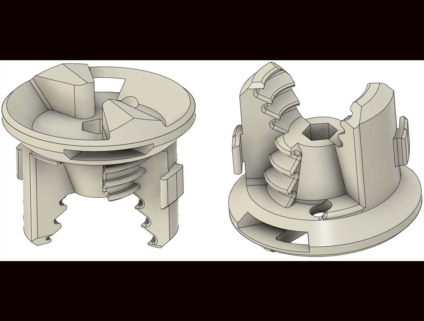
The SSS-Joint is an interlocking joint system for joining structure components such as struts, flat truss frames, and volumetric truss bays together to build bigger and more complex structure systems. The SSS-Joint interface can be applied to various connection scenarios commonly found in truss structure assembly, including but not limited to strut-to-strut connections, strut-to-node connections, and half-node-to-half-node connections. By incorporating half-node joints, the number of standalone components can be reduced by over 52%, and assembly steps can be decreased by over 65% compared to traditional truss tessellations without half-nodes.
In the current design, a single screwdriver can assemble all connections. The interlocking geometry of the SSS-joint features built-in guiding elements to aid the alignment process. Once in place, the screwdriver can rotate and engage with the spring-loaded captive lock-screw on the joint. The screwdriver tip does not need to be perfectly aligned, as the spring-loaded lock-screw will automatically pop into place within half a rotation after contact. This design dramatically reduces the complexity of the assembly process and eliminates the need for loose fasteners or specialized tools.
The SSS-joint offers a robust, lightweight, and scalable solution for modular structural assembly in space and terrestrial applications alike. The SSS-Joint has reached Technology Readiness Level (TRL) 5 (validated in a relevant environment) and is available for patent licensing.
Robotics Automation and Control

Reversible Androgynous Mechanical Fastener
The androgynous fastener is lightweight and facilitates assembly through simple actuation with large driver-positioning tolerance requirements. This fastener provides a high-strength, reversible mechanical connection and may be used in high strength-to-weight ratio structural systems, such as lattice structure systems. The androgynous fastener resists tensile and shear forces upon loading of the lattice structure system thereby ensuring that the struts of the lattice structure system govern the mechanical behavior of the system. The androgynous fastener eliminates building-block orientation requirements and allows assembly in all orthogonal build directions. This androgynous fastener may be captive in building-block structural elements thereby minimizing the logistical complexity of transporting additional fasteners. Integration of a plurality of the androgynous fasteners into a high performance, robotically managed, structural system reduces launch energy requirements, enables higher mission adaptivity and decreases system life-cycle costs. The androgynous fastener is beneficial in any application where robotic end effectors are used to join structural components (or other parts) together. It may be particularly desirable for applications requiring frequent movement of hardware to an assembly site to replace joint connections.
Robotics Automation and Control

New motors for next-generation in-space servicing
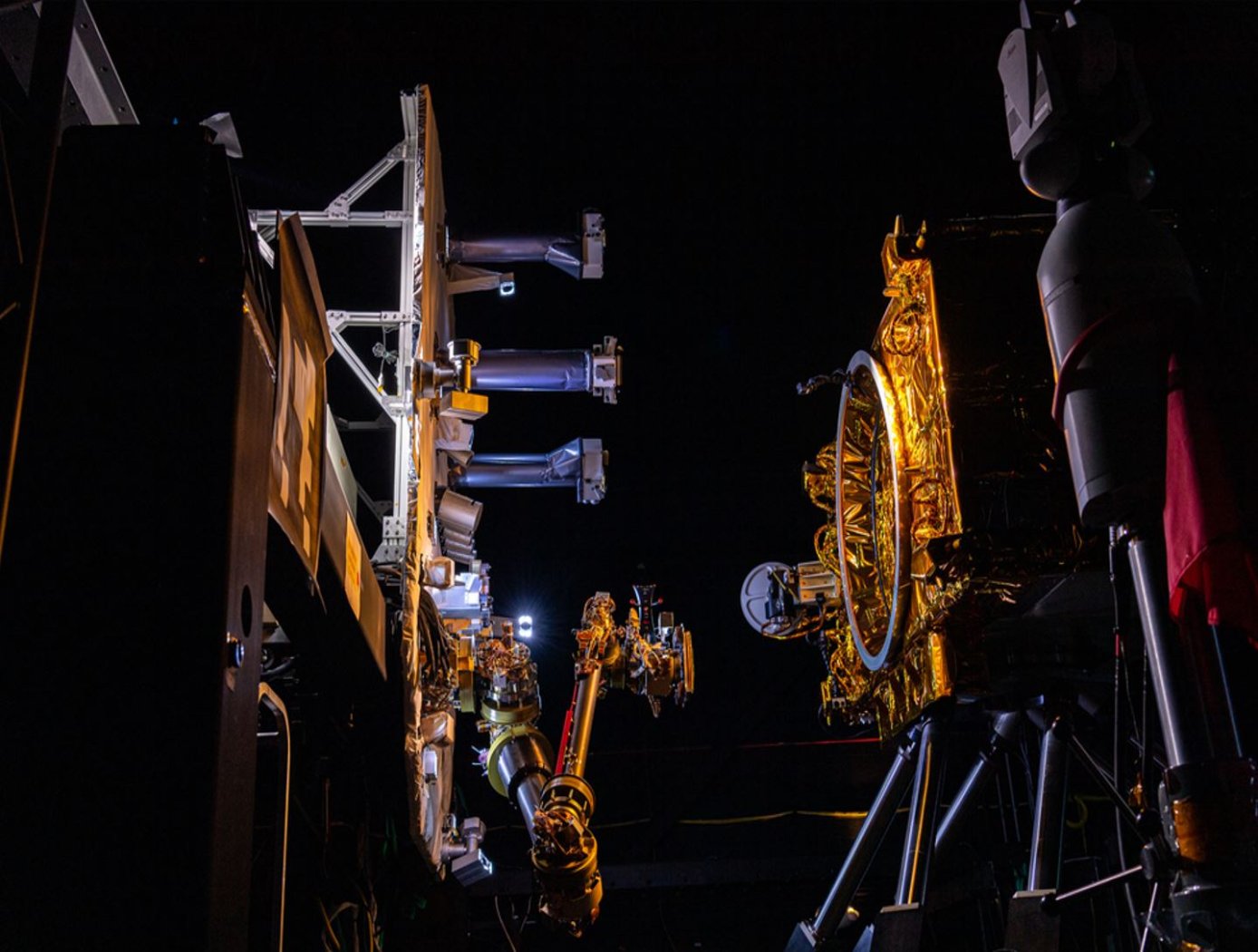
Satellites and other spacecraft require maintenance and service after being deployed in orbit, requiring a wide variety of tools that perform multiple maintenance tasks (grip, cut, refuel, etc.). Current drive systems for the tool interfaces on the robotic arms that perform these service tasks are not as robust nor packaged properly for use in the ATDS. The ATDS is one part of a larger in-space servicing system (example shown in the figure below) that must be versatile and perform multiple jobs.
Here, innovators at the NASA Goddard Space Flight Center have developed new BLDC motors to provide the torque necessary to drive the wide variety of tools needed for in-space servicing. The four motors provide torque to the coupler drive, linear drive, inner rotary drive, and outer rotary drive of the ATDS. The new BLDC motors will enable the tools attached to the ATDS to be operated in multiple modes of operation.
Each of the four motors have been customized with different speed and torque capabilities to meet the different performance requirements of the various actuator drive trains while maintaining a common gearhead across all the motors. Further, the packaging surrounding the motors has been tailored to reduce the overall weight of the motors and reduce the motor footprint to meet the needs of the ATDS. The BLDC motors for the ATDS are available for patent licensing.
Mechanical and Fluid Systems

Adaptive Camera Assembly
NASA’s adaptive camera assembly possesses a variety of unique and novel features. These features can be divided into two main categories: (1) those that improve “human factors” (e.g., the ability for target users with limited hand, finger, and body mobility to operate the device), and (2) those that enable the camera to survive harsh environments such as that of the moon. Some key features are described below. Please see the design image on this page for more information.
NASA’s adaptive camera assembly features an L-shaped handle that the Nikon Z9 camera mounts to via a quick connect T-slot, enabling tool-less install and removal. The handle contains a large tactile two-stage button for controlling the camera’s autofocus functionality as well as the shutter. The size and shape of the handle, as well as the location of the buttons, are optimized for use with a gloved hand (e.g., pressurized spacesuit gloves, large gloves for thermal protection, etc.). In addition, the assembly secures the rear LCD screen at an optimal angle for viewing when the camera is held at chest height. It also includes a button for cutting power – allowing for a hard power reset in the event of a radiation event. Two large button plungers are present, which can be used to press the picture review and "F4" buttons of the Nikon Z9 through an integrated blanket system that provides protection from dust and thermal environments.
Overall, NASA’s adaptive camera assembly provides a system to render the Nikon Z9 camera (a) easy to use by individuals with limited mobility and finger dexterity / strength, and (b) resilient in extreme environments.
Robotics Automation and Control

Visual Inspection Posable Invertebrate Robot (VIPIR)
Initially developed as a close quarters inspection tool capable of accessing hard to reach, tight, or visibly restricted, areas of satellites, the VIPIR system can be used to remotely inspect inaccessible locations such as behind a sheet of thermal blanketing material, into a satellites plumbing, or perhaps even deep inside the otherwise unreachable crevasses of a spacecraft bus. The VIPIR system incorporates a number of subassemblies for incredible operational freedom and capabilities for imaging and dissemination of componentry.
VIPIR’s Video Borescope Assembly (VBA) is a flexible snake-camera capable of multidirectional articulations, making steering and control simple and intuitive for an operator. The VBA also includes at least one imaging sensor and lighting to see in dark, confined spaces. Real-time, high-resolution visual information can be fed back to an operator for live analysis. A reel system extends and retracts the VBA with the use of a spool, and includes position indicators for deployment tracking. The Tendon Management System (TMS), not unlike human tendons, utilizes pulleys and tensioners to articulate the VBA in the confined spaces. A seal system ensures the VBA is free of contamination.
VIPIR underwent space-based testing on the ISS during the Robotic Refueling Phase 2 (RRM-2) mission designed to showcase and test several NASA advanced robotic satellite servicing technologies. During this mission, VIPIR demonstrated state-of-the-art near and midrange inspection capabilities. NASA’s VIPIR system is available for licensing to industry, and may be desirable to companies focused on satellite servicing, on-orbit assembly, and other applications requiring detailed inspection of assets in space.
Robotics Automation and Control

Method for discrete assembly of Cuboctahedron Lattice Materials
The novel technology is a method for the design, manufacture, and assembly of modular lattice structure based mechanical metamaterials composed of cuboctahedron unit cells. The main parameters for determining the behavior of an architected lattice material are 1. Lattice geometry: base unit cell topology defines joint connectivity and informs general lattice behavior (e.g. bending or stretch dominated), which can then be used for performance prediction relative to constituent material and density. Cell size (edge length) and edge thickness (cross section) can be used to calculate relative density; 2. Base constituent material: solid properties (mechanical, thermal, electrical, etc.) are used to calculate effective properties of resulting lattice, as well as to inform manufacturing processes.
The invention relates particularly to a cuboctahedral lattice geometry, which can be decomposed into face connected cuboctahedrons. The material used is determined by the manufacturing process, such as injection molding. This offers a range of high-performance options such as glass fiber and carbon fiber reinforced polymer (GFRP, CFRP) composites. The size of the lattice can vary based on the application. Molded individual faces (bottom left figure) are then assembled into the cuboctahedron voxel building block (bottom right figure). This assembly can be achieved with a number of methods, including permanent methods such as welding or gluing, or reversible methods such as bolting or riveting.
Materials and Coatings

Novel Shape Memory Composite Substrate
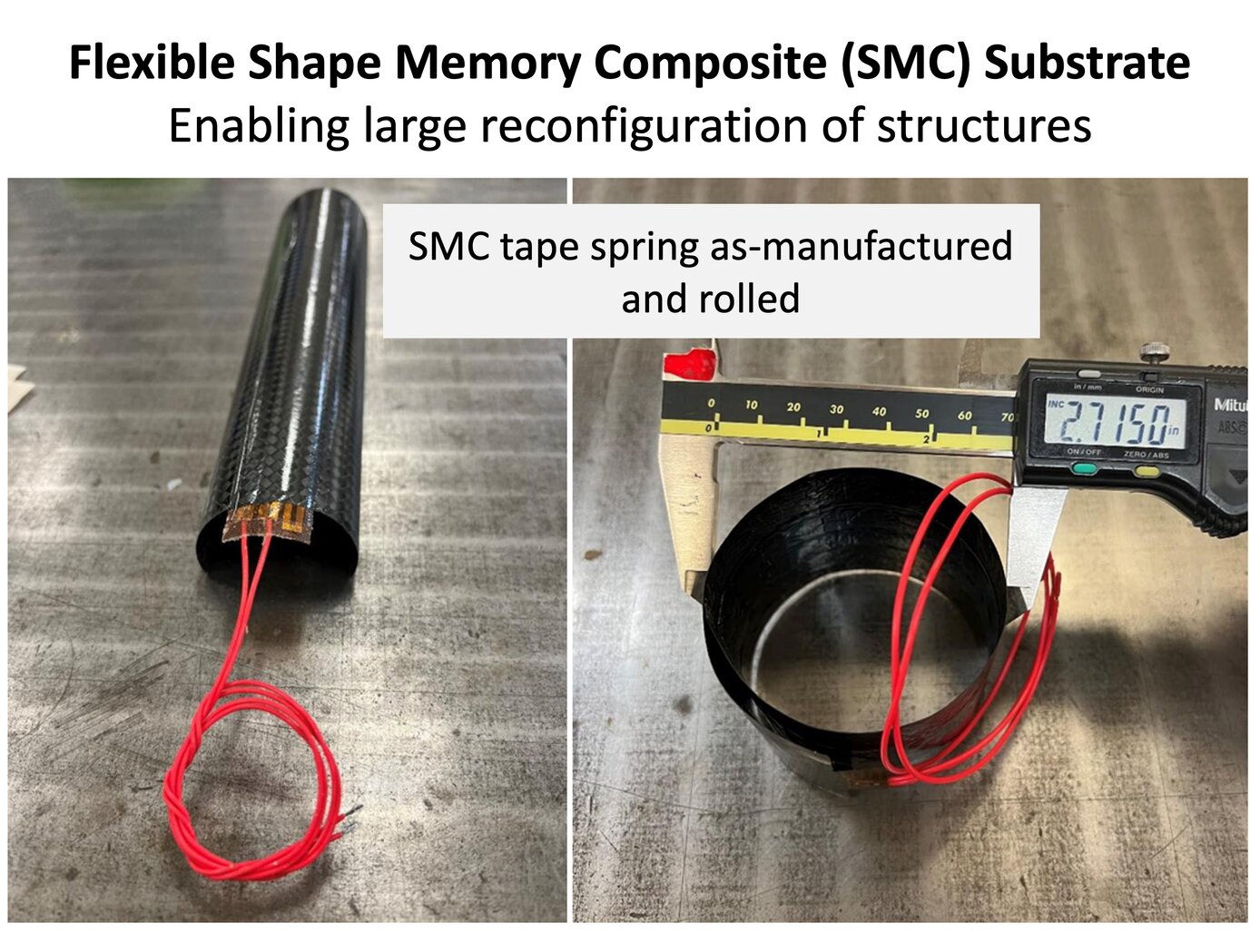
The new SMC substrate has four components: a shape memory polymer separately developed at NASA Langley; a stack of thin-ply carbon fiber sheets; a custom heater and heat spreader between the SMC layers; and integrated sensors (temperature and strain). The shape memory polymer allows the as-fabricated substrate to be programmed into a temporary shape through applied force and internal heating. In the programmed shape, the deformed structure is in a frozen state remaining dormant without external constraints. Upon heating once more, the substrate will return slowly (several to tens of seconds) to the original shape (shown below).
The thin carbon fiber laminate and in situ heating solve three major pitfalls of shape memory polymers: low actuation forces, low stiffness and strength limiting use as structural components, and relatively poor heat transfer. The key benefit of the technology is enabling efficient actuation and control of the structure while being a structural component in the load path. Once the SMC substrate is heated and releases its frozen strain energy to return to its original shape, it cools down and rigidizes into a standard polymer composite part. Entire structures can be fabricated from the SMC or it can be a component in the system used for moving between stowed and deployed states (example on the right). These capabilities enable many uses for the technology in-space and terrestrially.


