Search
manufacturing

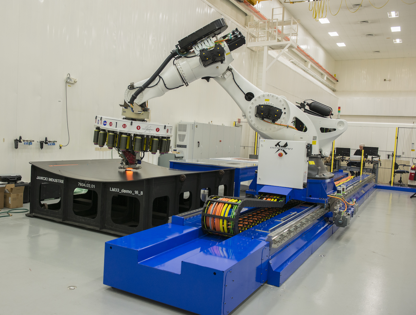
AERoBOND: Large-scale Composite Manufacturing
This technology (AERoBOND) enables the assembly of large-scale, complex composite structures while maintaining predictable mechanical and material properties. It does so by using a novel barrier-ply technology consisting of an epoxy resin/prepreg material with optimal efficiency, reliability, and performance. The barrier-ply materials prevent excessive mixing between conventional composite precursors and stoichiometrically-offset epoxy precursors during the cure process by forming a gel early in the cure cycle before extensive mixing can occur. The barrier ply is placed between the conventional laminate preform and the stoichiometrically-offset ply or plies placed on the preform surface, thus preventing excessive mass transfer between the three layers during the cure process. In practice, the barrier ply could be combined with the offset ply to be applied as a single, multifunctional surfacing layer enabling unitized assembly of large and complex structures. The AERoBOND method is up to 40% faster than state-of-the-art composite manufacturing methods, allows for large-scale processing of complex structures, eliminates the potential for weak bond failure modes, and produces composites with comparable mechanical properties as compared with those prepared by co-cure.
sensors

Solid State Carbon Dioxide (CO2) Sensor
The technology is a solid state, Carbon Dioxide (CO2) sensor configured for sensitive detection of CO2 having a concentration within the range of about 100 Parts per Million (ppm) and 10,000 ppm in both dry conditions and high humidity conditions (e.g., > 80% relative humidity). The solid state CO2 sensor achieves detection of high concentrations of CO2 without saturation and in both dynamic flow mode and static diffusion mode conditions. The composite sensing material comprises Oxidized Multi-Walled Carbon Nanotubes (O-MWCNT) and a metal oxide, for example O-MWCNT and iron oxide (Fe2O3) nanoparticles. The composite sensing material has an inherent resistance and corresponding conductivity that is chemically modulated as the level of CO2 increases. The CO2 gas molecules absorbed into the carbon nanotube composites cause charge-transfer and changes in the conductive pathway such that the conductivity of the composite sensing material is changed. This change in conductivity provides a sensor response for the CO2 detection. The solid state CO2 sensor is well suited for automated manufacturing using robotics and software controlled operations. The solid state CO2 sensor does not utilize consumable components or materials and does not require calibration as often as conventional CO2 sensors. Since the technology can be easily integrated into existing programmable electronic systems or hardware systems, the calibration of the CO2 sensor can be automated.
manufacturing
Calibration System for Automated Fiber Placement
NASA's new calibration system is a proprietary method to quickly design and make predictable and repeatable gap-and-overlap defects when employing AFP. The system creates defects within the course of layup with known sizes, geometries, and locations. Using this defect-creation technique, one can now accurately quantify the ability to detect defects on inspection systems, perform accurate risk assessments, and calibrate in-situ inspection equipment to specific materials. The equipment that makes the defects can be efficiently and inexpensively 3D printed. This technique is currently being used to successfully calibrate NASA's in situ inspection system for their AFP equipment.
AFP is experiencing increasing adoption in aerospace, automotive, and other industries that leverage large-scale advanced composite components. NASA's new AFP calibration system could be very useful to companies that develop and manufacture AFP machines or AFP machine inspection equipment to improve the quality of their products in a provable manner. Furthermore, users of AFP machines may find value in the tool for creating their own calibration standards.
Materials and Coatings
Carbon Fiber-Carbon Nanotube Yarn Hybrid Reinforcement
NASA's new material is a toughened triaxial braid made from ductile carbon nanotube (CNT) yarn hybridized with carbon fiber, which is ultimately used as reinforcement material to make toughened polymer matrix composites. The CNT yarn component of the reinforcement is solely responsible for adding toughness, while the processes used to optimize the fiber braiding parameters and tensile properties of the carbon fiber-CNT yarn hybrid tow material determine the overall improvement in tensile strength for resin impregnated fiber tows. Bundles of continuous carbon nanotube yarns are combined with a similar format of carbon fiber, yielding an easily scalable process.
Advantages of the material include reduced cost by eliminating use of toughening agents, increased ability to conform to highly complex geometries, greater environmental stability compared to aramid fiber reinforcements such as Kevlar, and possibly decreased density. Many hybrid reinforcements exhibit interfacial compatibility issues, which could lead to premature failure via crack propagation at the polymer matrix interface. In contrast, chemical similarities between the CNT yarn and carbon fiber constituents impart NASA's hybrid reinforcement material with excellent interfacial compatibility.
Potential applications include aerospace components, composite pressure vessels, wind turbine blades, automotive components, prosthetics, sporting equipment, construction reinforcement material, and other use-cases where strength-to-weight ratio is of utmost importance.

