Search
materials and coatings
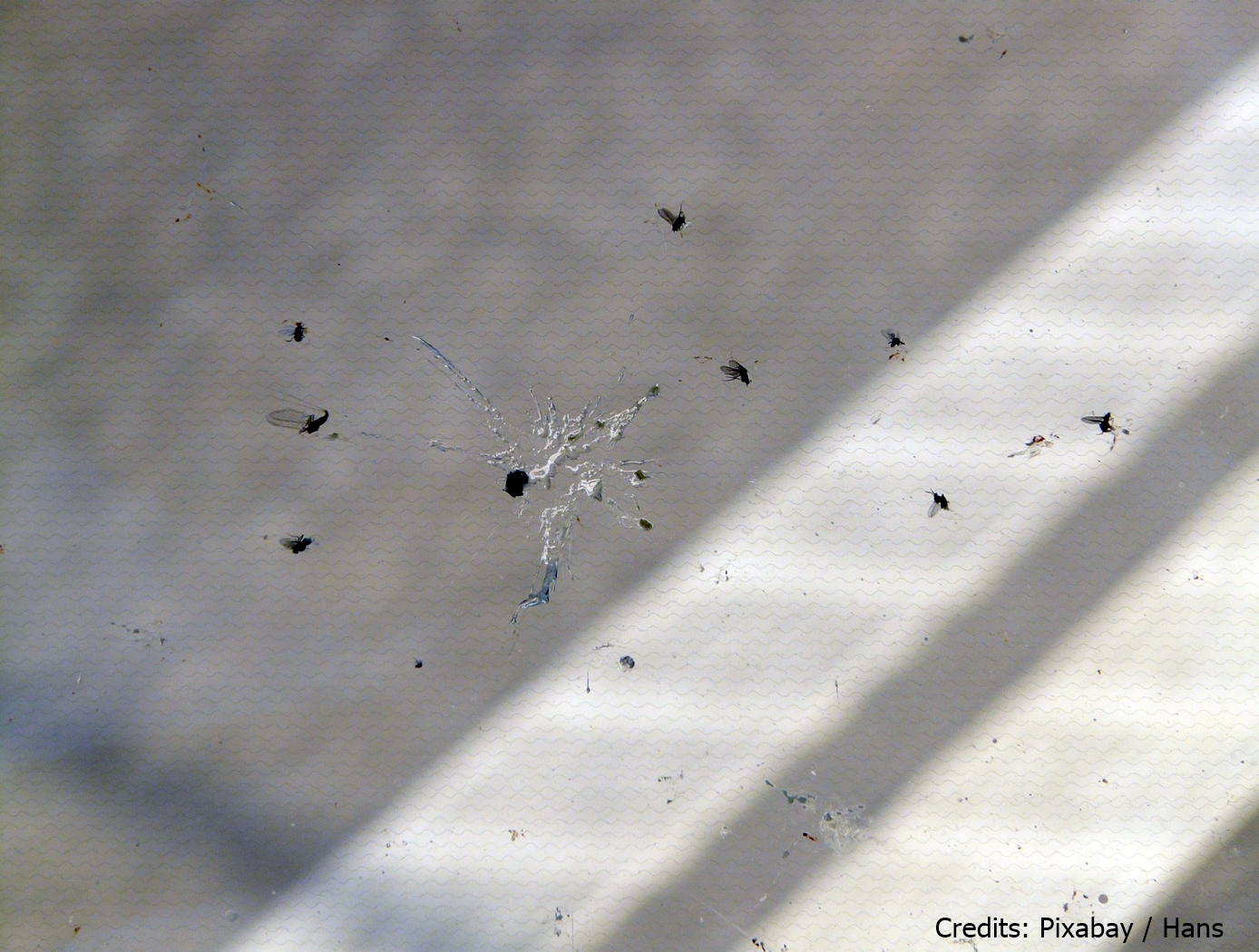
Hydrophobic Epoxy Coating for Insect Adhesion Mitigation
This technology is a copolymeric epoxy coating that is loaded with a fluorinated aliphatic chemical species and nano- to microscale particle fillers. The coating was developed as a hydrophobic and non-wetting coating for aerodynamic surfaces to prevent accumulation of insect strike remains that can lead to natural laminar flow disruption and aerodynamic inefficiencies. The coating achieves hydrophobicity in two ways. First, the fluorinated aliphatic chemical species are hydrophobic surface modification additives that preferentially migrate to the polymer surface that is exposed to air. Secondly, the incorporation of particle fillers produces a micro-textured surface that displays excellent resistance to wetting. Combined, these two factors increase hydrophobicity and can also be used to readily generate superhydrophobic surfaces.
materials and coatings

Chemical and Topographical Surface Modifications for Insect Adhesion Mitigation
The technology is a method of mitigating insect residue adhesion to various surfaces upon insect impact. The process involves topographical modification of the surface using laser ablation patterning followed by chemical modification or particulate inclusion in a polymeric matrix. Laser ablation patterning is performed by a commercially available laser system and the chemical spray deposition is composed of nanometer sized silica particles with a hydrophobic solution (e.g. heptadecafluoro-1,1,2,2-tetrahydrodecyltriethoxysilane) in an aqueous ethanol solution. Both topographic and chemical modification of the substrate is necessary to achieve the desired performance.
Environment
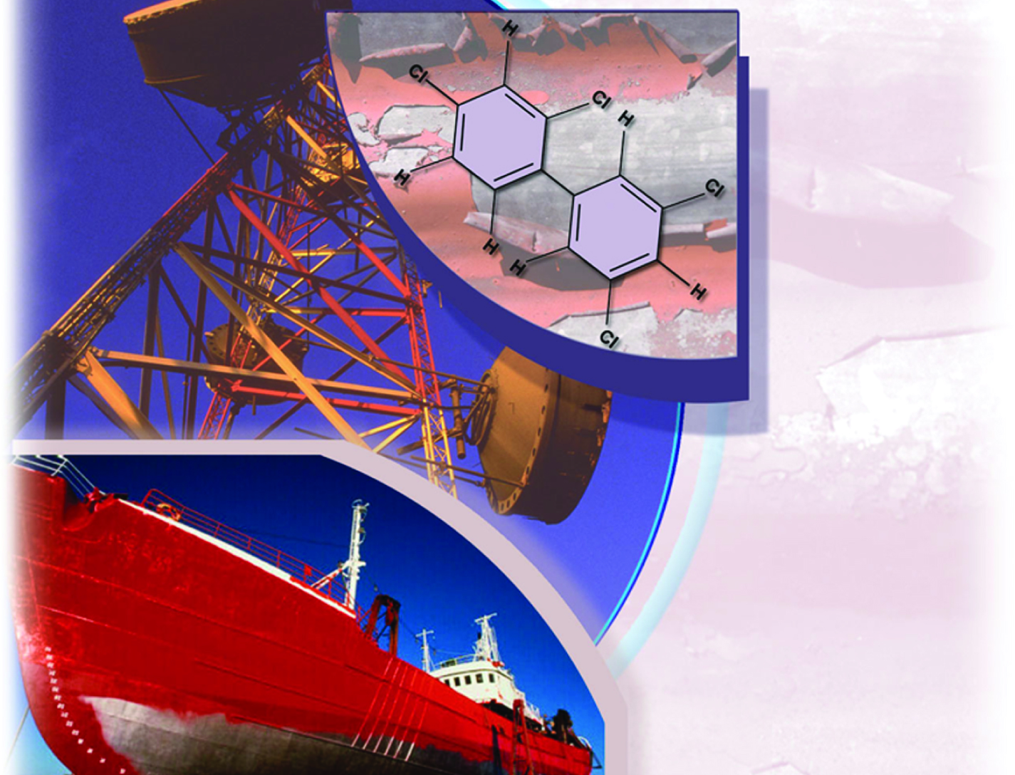
Activated Metal Treatment System (AMTS) for Paints
PCBs have been shown to cause cancer in animals and to have other adverse effects on immune, reproductive, nervous, and endocrine systems. Although the production of PCBs in the United States has been banned since the late 1970s, many surfaces are still coated with PCB-laden paints. The presence of PCBs in paints adds complexity and expense for disposal. Some treatment methods (e.g., use of solvents, physical removal via scraping) are capable of removing PCBs from surfaces, but these technologies create a new waste stream that must be treated. Other methods, like incineration, can destroy the PCBs but destroy the painted structure as well, preventing reuse.
To address limitations with traditional abatement methods for PCBs in paints, researchers at NASAs Kennedy Space Center (KSC) and the University of Central Florida have developed the Activated Metal Treatment System (AMTS) for Paints. This innovative technology consists of a solvent solution (e.g., ethanol, d-limonene) that contains an activated zero-valent metal.
AMTS is first applied to the painted surface either using spray-on techniques or wipe-on techniques. The solution then extracts the PCBs from the paint. The extracted PCBs react with the microscale activated metal and are degraded into benign by-products. This technology can be applied without removing the paint or dismantling the painted structure. In addition, the surface can be reused following treatment.
Electrical and Electronics
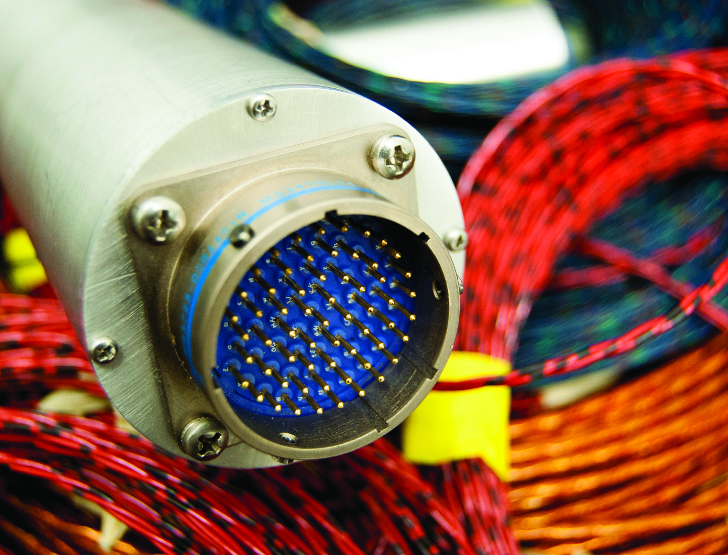
In Situ Wire Damage Detection and Rerouting System
The tester was designed to monitor electrical faults in either online or offline modes of operation. In the online mode, wires are monitored without disturbing their normal operation. A cable can be monitored several times per second in the offline mode, and once per second in the online mode. The online cable fault locator not only detects the occurrence of a fault, but also determines the type of fault (short/open/intermittent) and the location of the fault. This enables the detection of intermittent faults that can be repaired before they become serious problems. Since intermittent faults occur mainly during operations, a built-in memory device stores all relevant fault data. This data can be displayed in real time or retrieved later so maintenance and repairs can be completed without spending countless hours attempting to pinpoint the source of the problem.
Hardware and algorithms have also been developed to safely, efficiently, and autonomously transfer electrical power and data connectivity from an identified damaged/defective wire in a cable to an alternate wire path. This portion of the system consists of master and slave units that provide the diagnostic and rerouting capabilities. A test pulse generated by the master unit is sent down an active wire being monitored by the slave unit. When the slave unit detects the test pulse, it routes the pulse back to the master unit through a communication wire. When the master unit determines that a test pulse is not being returned, it designates that wire as faulty and reroutes the circuit to a spare wire.
manufacturing

Ultrasonic Stir Welding
Ultrasonic Stir Welding is a solid state stir welding process, meaning that the weld work piece does not melt during the welding process. The process uses a stir rod to stir the plasticized abutting surfaces of two pieces of metallic alloy that forms the weld joint. Heating is done using a specially designed induction coil. The control system has the capability to pulse the high-power ultrasonic (HPU) energy of the stir rod on and off at different rates from 1-second pulses to 60-millisecond pulses. This pulsing capability allows the stir rod to act as a mechanical device (moving and stirring plasticized nugget material) when the HPU energy is off, and allowing the energized stir rod to transfer HPU energy into the weld nugget (to reduce forces, increase stir rod life, etc.) when the HPU energy is on. The process can be used to join high-melting-temperature alloys such as titanium, Inconel, and steel.
materials and coatings

A New Class of Strong and Flexible Carbon Fiber Reinforced Phenolic Composites
This unique approach modifies the phenolic polymer network by adding thermoplastic molecules with flexible segments such as aliphatic carbon and siloxane. The thermoplastic molecules are terminated with bifunctional groups that can directly react with the phenolic under the curing condition to form chemical bonds. Further incorporation of these segments can be facilitated by a relay reaction of a second molecular component which can bond with both the first flexible segments and the phenolic network. The selections of flexible, thermoplastic segments are based on desired properties, which include flexibility, ablative, an charring ability, heat resistance, and low catalycity.
The modified phenolic is a truly molecular composite in which flexible segments are connected with the phenolic network through strong chemical bonds and are uniformly distributed among the networks. This feature renders a uniform toughening/strengthening effect without compromising the lightweight nature of the materials. The process is also feasible to scale up and amenable for manufacturing.
Materials and Coatings
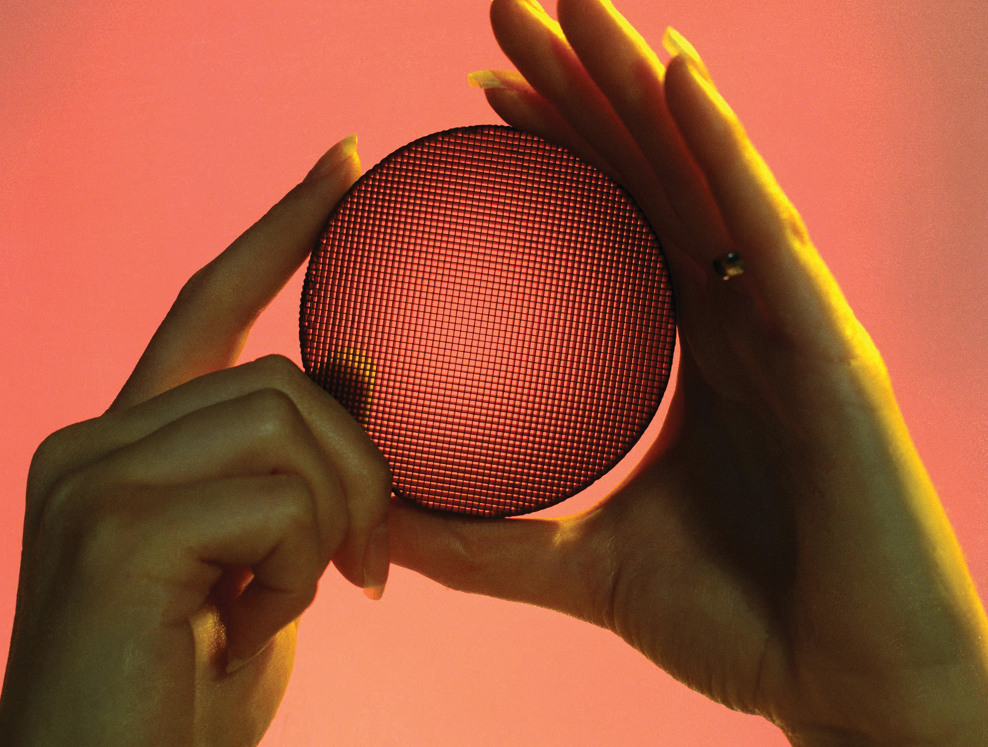
Low-Temperature Oxidation/
Reduction Catalysts
The low-temperature oxidation catalyst technology employs a novel catalyst formulation, termed platinized tin oxide (Pt/SnOx). The catalysts can be used on silica gel and cordierite catalyst supports, and the latest developments provide sprayable formulations for use on a range of support types and shapes. Originally developed for removal of CO, the catalyst has also proven effective for removal of formaldehyde and other lightweight hydrocarbons.
NASA researchers have also extended the capability to include reduction of NOx as well as developed advanced chemistries that stabilized the catalyst for automotive catalytic converters via the engineered addition of other functional components. These catalyst formulations operate at elevated temperatures and have performed above the EPA exhaust standards for well beyond 25,000 miles. In addition, the catalyst can be used in diesel engines because of its ability to operate over an increased temperature range.
For use as a gas sensor, the technology takes advantage of the exothermic nature of the catalytic reaction to detect formaldehyde, CO, or hydrocarbons, with the heat being produced proportional to the amount of analyte present.
Mechanical and Fluid Systems

Fluid Structure Coupling Technology
FSC is a passive technology that can operate in different modes to control vibration:
Harmonic absorber mode: The fluid can be leveraged to act like a classic harmonic absorber to control low-frequency vibrations. This mode leverages already existing system mass to decouple a structural resonance from a discrete frequency forcing function or to provide a highly damped dead zone for responses across a frequency range.
Shell mode: The FSC device can couple itself into the shell mode and act as an additional spring in a series, making the entire system appear dynamically softer and reducing the frequency of the shell mode. This ability to control the mode without having to make changes to the primary structure enables the primary structure to retain its load-carrying capability.
Tuned mass damper mode: A small modification to a geometric feature allows the device to act like an optimized, classic tuned mass damper.
Aerospace

Foot Pedal Controller
The Foot Pedal Controller enables an operator of a spacecraft, aircraft, or watercraft, or a simulation of one in a video game, to control all translational and rotational movement using two foot pedals. This novel technology allows control across all six degrees of freedom, unlike any technology on the market. The components of the technology are a support structure, a left foot pedal, a right foot pedal, and supporting electronics. The Foot Pedal Controller is intuitive, easy to learn, and has ergonomic features that accommodate and stabilize the operator's feet. A working prototype is available to demonstrate key technology features to potential licensees.
The Foot Pedal Controller technology could be used in designs for the flight deck of the future, video game controls, drone operations and flight simulators. This technology can be useful in any application where it is preferred or desirable to use the feet to control motion rather than using the hands. A potential market could be foot control of equipment by people with arm or hand disabilities. A unique aspect of the innovation is the consideration of natural foot mechanics in the design and placement of the sensors and actuators to reduce operator fatigue. The axes of rotation of the Controller align with the joints of the foot so the foot moves naturally to control the movement of the craft. NASA seeks collaborations with companies interested in licensing and partnering to further develop and commercialize the technology.
sensors

Infrasound Sensor Technology
Large aircraft can generate air vortices in their wake, turbulence that can prove hazardous to aircraft that follow too closely. Because wake vortices are invisible, all takeoffs at busy airports are spaced several minutes apart. This separation gives the vortices time to dissipate, even though they only occur 10% of the time, with resulting loss of operational efficiency. Similarly, clear air turbulence is invisible and can also be hazardous to aircraft. By detecting such disturbances through their infrasound emissions, precautions can be taken to avoid them.
Other phenomena can be detected through infrasound, including tornadoes, helicopters on the other side of mountains, underground nuclear explosions and digging tunnels. Through the unique properties of infrasound, many of these can be detected from hundreds of miles away. NASA's infrasound sensor is a highly refined microphone that is capable of detecting acoustic waves from 20 Hz down to dc, the infrasound range. The design is robust and compact, eliminating the bulk and weight found in other technologies. Where most alternative methods are restricted to certain weather conditions and locations,
the NASA sensor filters noise from wind and other sources, allowing its use under any weather or geographic conditions.


