Search
Robotics Automation and Control

Anonymous Feature Processing for Enhanced Navigation
This concept presents a new statistical likelihood function and Bayesian analysis update for non-standard measurement types that rely on associations between observed and cataloged features. These measurement types inherently contain non-standard errors that standard techniques, such as the Kalman filter, make no effort to model, and this mismodeling can lead to filter instability and degraded performance.
Vision-based navigation methods utilizing the Kalman filter involve a preprocessing step to identify features within an image by referencing a known catalog. However, errors in this pre-processing can cause navigation failures. AFP offers a new approach, processing points generated by features themselves without requiring identification. Points such as range or bearing are directly processed by AFP.
Operating on finite set statistics principles, AFP treats data as sets rather than individual features. This enables simultaneous tracking of multiple targets without feature labeling. Unlike the sequential processing of the Kalman filter, AFP processes updates in parallel, independently scoring each output based on rigorous mathematical functions. This parallel processing ensures robust navigation updates in dynamic environments, and without requiring an identification algorithm upstream of the filter.
Computational simulations conducted at Johnson Space Center demonstrate that AFP's performance matches or exceeds that of the ideal Kalman filter, even under non-ideal conditions. Anonymous Feature Processing for Enhanced Navigation is at a technology readiness level (TRL) 4 (component and/or breadboard validation in laboratory environment) and is now available for patent licensing. Please note that NASA does not manufacture products itself for commercial sale.
Robotics Automation and Control

Lunar Surface Navigation System
NASA’s reverse-ephemeris lunar navigation system is a concept for determining position on the lunar surface based on known orbits of satellites. In conventional GPS navigation systems, the GPS satellite transmits ephemeris data to a receiver on earth for determining position at the receiver location. Whereas for the reverse-ephemeris approach the receiver becomes the transmitter, and the satellite instead serves more as a fixed reference position with a known ephemeris. This simplifies the satellite requirements and also mitigates potential navigational disruptions that can otherwise arise in navigation systems that utilize satellite-based communications, for example from interference, jamming, etc.
The design consists of lunar surface S-Band (2,400 – 2,450 MHz) 10 W transceivers ranging with analog translating transponders on a three-satellite constellation in frozen elliptical orbits to provide continuous coverage with service to 300 simultaneous users over 1.8 MHz of bandwidth at the transponder. Digital bases systems are possible too. As compared to GPS-based navigation requiring four or more satellites costing 100’s of millions of dollars, the new NASA concept is based on using only three smallsats.
Robotics Automation and Control

Adaptive wind estimation for small unmanned aerial systems using motion data
The technology presents an on-board estimation, navigation and control architecture for multi-rotor drones flying in an urban environment. It consists of adaptive algorithms to estimate the vehicle's aerodynamic drag coefficients with respect to still air and urban wind components along the flight trajectory, with guaranteed fast and reliable convergence to the true values. Navigation algorithms generate feasible trajectories between given way-points that take into account the estimated wind. Control algorithms track the generated trajectories as long as the vehicle retains a sufficient number of functioning rotors that are capable of compensating for the estimated wind. The technology provides a method of measuring wind profiles on a drone using existing motion sensors, like the inertial measurement unit (IMU), rate gyroscope, etc., that are observably necessary for any drone to operate. The algorithms are used to estimate wind around the drone. They can be used for stability or trajectory calculations, and are adaptable for use with any UAV regardless of the knowledge of weight and inertia. They further provide real-time calculations without additional sensors. The estimation method is implemented using onboard computing power. It rapidly converges to true values, is computationally inexpensive, and does not require any specific hardware or specific vehicle maneuvers for the convergence. All components of this on-board system are computationally effective and are intended for a real time implementation. The method's software is developed in a Matlab/Simulink environment, and has executable versions, which are suitable for majority of existing onboard controllers. The algorithms were tested in simulations.
Aerospace

Vision-based Approach and Landing System (VALS)
The novel Vision-based Approach and Landing System (VALS) provides Advanced Air Mobility (AAM) aircraft with an Alternative Position, Navigation, and Timing (APNT) solution for approach and landing without relying on GPS. VALS operates on multiple images obtained by the aircraft’s video camera as the aircraft performs its descent. In this system, a feature detection technique such as Hough circles and Harris corner detection is used to detect which portions of the image may have landmark features. These image areas are compared with a stored list of known landmarks to determine which features correspond to the known landmarks. The world coordinates of the best matched image landmarks are inputted into a Coplanar Pose from Orthography and Scaling with Iterations (COPOSIT) module to estimate the camera position relative to the landmark points, which yields an estimate of the position and orientation of the aircraft. The estimated aircraft position and orientation are fed into an extended Kalman filter to further refine the estimation of aircraft position, velocity, and orientation. Thus, the aircraft’s position, velocity, and orientation are determined without the use of GPS data or signals. Future work includes feeding the vision-based navigation data into the aircraft’s flight control system to facilitate aircraft landing.
Instrumentation

Reconfigurable Local Oscillator for Coherent Optical Detection
The innovation expands the range of signals that coherent optical receivers can detect. Unlike traditional systems with fixed LOs, this approach allows real-time adjustments to an LO’s properties, such as frequency, phase, polarization, amplitude, spatial mode, or timing, to better match incoming signals. These adjustments improve measurement accuracy and signal recovery in various scenarios, such as shifting heterodyne frequencies into the receiver’s bandwidth or adapting to different signal polarizations. The innovation lies in the ability to switch an LO's configurations on the fly using technologies like fiber-optic or integrated photonic switches, as well as other methods like optical modulation or tunable delay lines. This dynamic capability allows coherent receivers to switch seamlessly between range-Doppler and Doppler-only modes. As a result, a single system can track both nearby, slow-moving targets and distant, high-velocity objects (up to 20+ km/s) while operating with a compact, low-speed receiver (<1 GHz). This versatility significantly enhances the performance and adaptability of advanced optical sensing and communication systems.
While initially developed for NASA’s Navigation Doppler LiDAR project, this invention can support advanced signal detection applications across several industries, including optical communications, aerospace, structural health monitoring, and autonomous vehicles. By enabling real-time reconfiguration, the invention offers improved signal recovery, enhanced sensitivity, and broader system adaptability for challenging detection environments. The technology has gone through prototype development and is currently at TRL 3 (proof-of-concept), and the reconfigured LO is available for patent licensing.
Optics
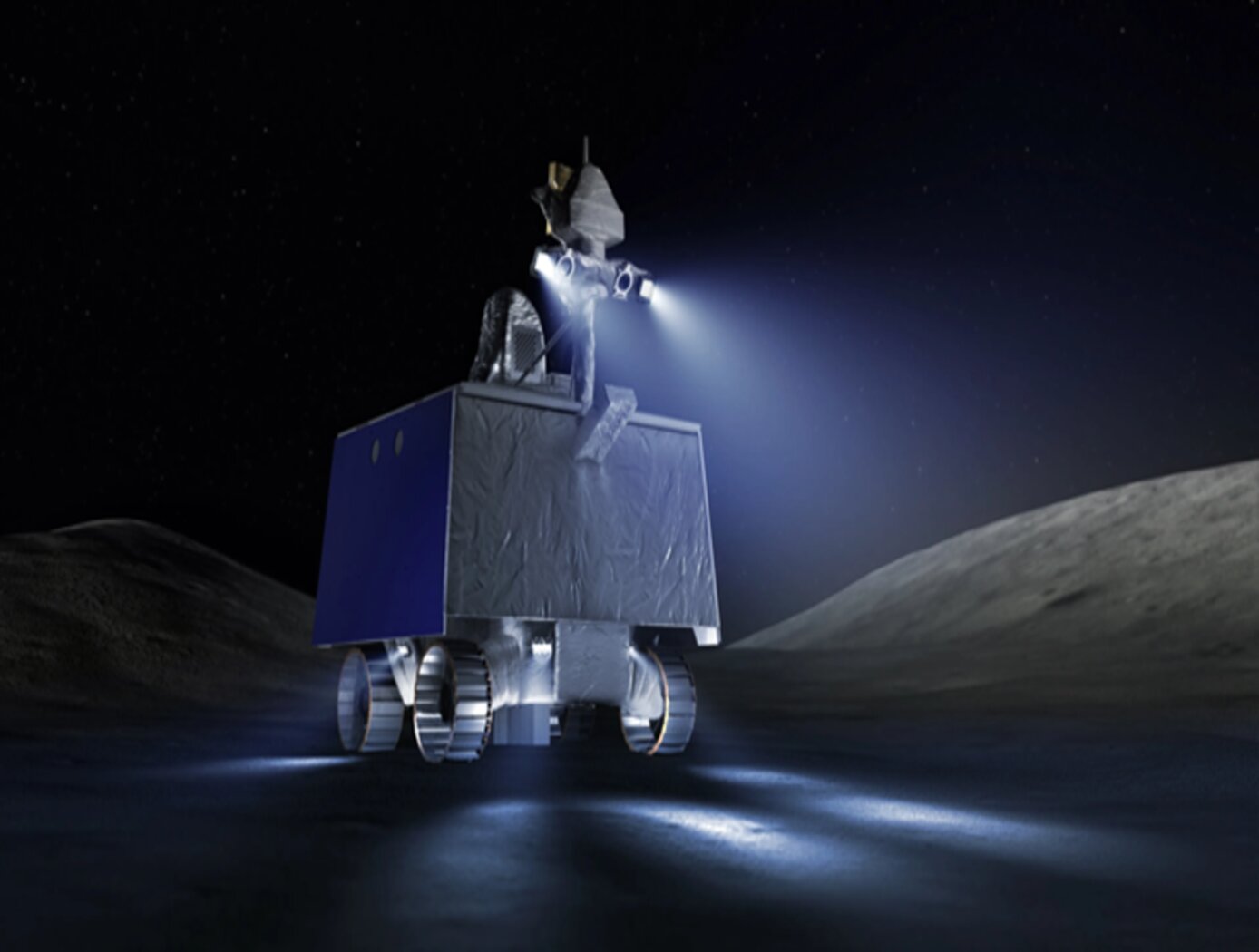
3D Lidar for Improved Rover Traversal and Imagery
The SQRLi system is made up of three major components including the laser assembly, the mirror assembly, and the electronics and data processing equipment (electronics assembly) as shown in the figure below. The three main systems work together to send and receive the lidar signal then translate it into a 3D image for navigation and imaging purposes.
The rover sensing instrument makes use of a unique fiber optic laser assembly with high, adjustable output that increases the dynamic range (i.e., contrast) of the lidar system. The commercially available mirror setup used in the SQRLi is small, reliable, and has a wide aperture that improves the field-of-view of the lidar while maintaining a small instrument footprint. Lastly, the data processing is done by an in-house designed processor capable of translating the light signal into a high-resolution (sub-millimeter) 3D map. These components of the SQRLi enable successful hazard detection and navigation in visibility-impaired environments.
The SQRLi is applicable to planetary and lunar exploration by unmanned or crewed vehicles and may be adapted for in-space servicing, assembly, and manufacturing purposes. Beyond NASA missions, the new 3D lidar may be used for vehicular navigation in the automotive, defense, or commercial space sectors. The SQRLi is available for patent licensing.
Aerospace

Method And System for Enhancing Vehicle Performance and Design Using Parametric Modeling and Gradient-Based Control Integration
The parametric modeling system allows for the integrated design and optimization of aerospace vehicles by unifying physical and control subsystems within a single computational model. The system includes representations of the vehicle’s geometry, structural load, propulsion, energy storage, and GNC systems. The system performs sensitivity analysis on key performance metrics (e.g., fuel consumption, heat load, and mechanical forces) to determine how changes in design parameters affect overall performance. By incorporating real-world conditions, such as wind variations and sensor noise, the system allows for the use of real-time feedback to refine vehicle designs. The optimization process uses a gradient-based algorithm to iteratively adjust parameters so that constraints such as structural integrity, thermal protection, and fuel capacity are met. The system generates a Pareto front representing trade-offs between performance metrics that allow engineers to visualize optimal designs for different mission profiles, which enhances design accuracy while reducing the need for expensive physical testing.
Information Technology and Software
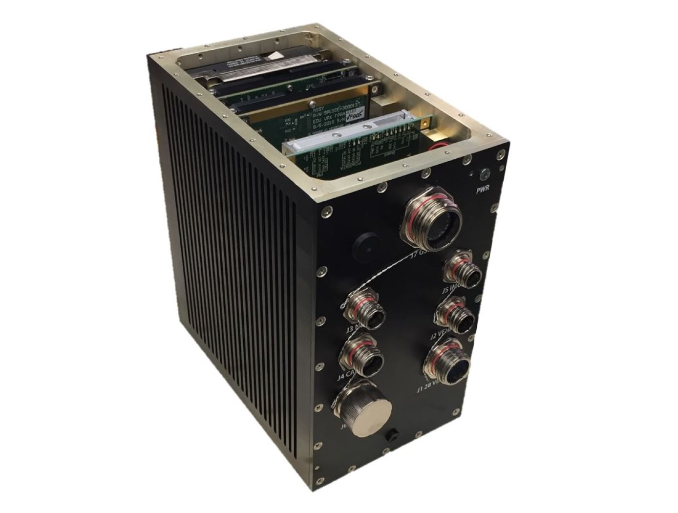
Unique Datapath Architecture Yields Real-Time Computing
The DLC platform is composed of three key components: a NASA-designed field programmable gate array (FPGA) board, a NASA-designed multiprocessor on-a-chip (MPSoC) board, and a proprietary datapath that links the boards to available inputs and outputs to enable high-bandwidth data collection and processing.
The inertial measurement unit (IMU), camera, Navigation Doppler Lidar (NDL), and Hazard Detection Lidar (HDL) navigation sensors (depicted in the diagram below) are connected to the DLC’s FPGA board. The datapath on this board consists of high-speed serial interfaces for each sensor, which accept the sensor data as input and converts the output to an AXI stream format. The sensor streams are multiplexed into an AXI stream which is then formatted for input to a XAUI high speed serial interface. This interface sends the data to the MPSoC Board, where it is converted back from the XAUI format to a combined AXI stream, and demultiplexed back into individual sensor AXI streams. These AXI streams are then inputted into respective DMA interfaces that provide an interface to the DDRAM on the MPSoC board. This architecture enables real-time high-bandwidth data collection and processing by preserving the MPSoC’s full ability.
This sensor datapath architecture may have other potential applications in aerospace and defense, transportation (e.g., autonomous driving), medical, research, and automation/control markets where it could serve as a key component in a high-performance computing platform and/or critical embedded system for integrating, processing, and analyzing large volumes of data in real-time.
Robotics Automation and Control

Robotic System for Infra-structure Reconnaissance
The robotic system is comprised of six main components: the orb that performs the reconnaissance, an orb injector housing that attaches to a piping network, a tether and reel subsystem that attaches to the back of the injector housing, a fluid injection subsystem that attaches toward the front of the injector housing, an external power and data subsystem, and associated control and monitoring software.
Usage of the system begins with an operator attaching the injector housing, with the orb stowed inside, to a flanged gate valve belonging to the piping network of concern. Requisite power, data, and fluid subsystems are attached, and the system is energized for usage. The orb is released via the tether and reel, and a controlled fluid force is imparted on the orb to help guide it along its mission. The tether supplies power and guidance to the orb, and relays real-time data back to the operator.
The orb’s interior features a modular plug-and-play architecture which may comprise COTS instrumentation for reconnaissance or investiga-tion, LIDAR, and inertial measuring and motion sensors. This instru-mentation could be used in combination with other sub-systems such as lighting, and core and sample retrieving mechanisms. These com-ponents are supported by other onboard devices such as a CPU, power source and controller, and data transmission encoders and multiplexers.
The Robotic System for Infrastructure Reconnaissance is at TRL 8 (actual system completed and "flight qualified" through test and demonstration), and is now available for licensing. Please note that NASA does not manufacture products itself for commercial sale.

