Search
environment
.jpg)
Tool for Rapid Identification of TCE in Plants
Plant uptake of TCE from contaminated groundwater is a well-known phenomenon. During the photosynthesis process, plants metabolize the TCE into a byproduct called trichloroacetic acid (TCAA). TCAA has been found to be a good indicator (or surrogate) molecule for the presence of TCE because it is more stable than TCE in plants. The hyperspectral estimator is being designed to detect TCAA. The method uses a white light that is directed at the surface of a plant's leaf. The interaction between the light and the leaf produces spectral signatures that are captured using a detector. A processor that will be coupled to the detector will compare these signatures to a library/database of signatures known to be indicators of the presence of TCAA (and thus TCE). The figure below on the left shows hyperspectral images captured using the method for leaves dosed with TCE over various time periods. These images are examples of response signatures that will eventually be built into the device's reference library/database. Proof-of-concept testing has shown that the hyperspectral estimator is capable of estimating the presence/absence of TCE in plant leaves with an accuracy of 80%. Efforts are now underway to further improve the accuracy of this method and to prototype the technology. The figure below on the right shows a diagram of the planned device.
Information Technology and Software

Interactive Diagnostic Modeling Evaluator
The i-DME is a computer-user interactive procedure for repairing the system model through its abstract representation, diagnostic matrix (D-matrix) and then translating the changes back to the system model. The system model is a schematic representation of faults, tests, and their relationship in terms of nodes and arcs. D-matrix is derived from the system models propagation paths as the relationships between faults and tests. When the relation exists between fault and test, it is represented as 1 in the D-matrix. To repair the D-matrix and wrapper/test logic by playing back a sequence of nominal and failure scenarios (given), the user sets the performance criteria and accepts/declines the proposed repairs. During D-matrix repair, the interactive procedure includes conditions ranging from modifying 0s and 1s in the matrix, adding/removing the rows (failure sources) columns (tests), or modifying test/wrapper logic used to determine test results. The translation of changes to the system model is done via a process which maps each portion of the D-matrix model to the corresponding locations in the system model. Since the mapping back to the system model is non-unique, more than one candidate system model repair can be suggested. In addition to supporting the modification, it provides a trace for each modification such that a rational basis for each decision can be verified.
instrumentation

Data Transfer for Multiple Sensor Networks
High-temperature sensors have been used in silicon carbide electronic oscillator circuits. The frequency of the oscillator changes as a function of changes in the sensor's parameters, such as pressure. This change is analogous to changes in the pitch of a person's voice. The output of this oscillator, and many others may be superimposed onto a single medium. This medium may be the power lines supplying current to the sensors, a third wire dedicated to data transmission, the airwaves through radio transmission, or an optical or other medium. However, with nothing to distinguish the identities of each source, this system is useless. Using frequency dividers and linear feedback shift registers, comprised of flip flops and combinatorial logic gates connected to each oscillator, unique bit stream codes may be generated. These unique codes are used to amplitude modulate the output of the sensor (both amplitude shift keying and on-off keying are applicable). By using a dividend of the oscillator frequency to generate the code, a constant a priori number of oscillator cycles will define each bit. At the receiver, a detected frequency will have associated with it a stored code pattern. Thus, a detected frequency will have a unique modulation pattern or "voice," disassociating it from noise and from other transmitting sensors. These codes may be pseudorandom binary sequences (PRBS), ASCII characters, gold codes, etc. The detected code length and frequency are measured, offering intelligent data transfer.
This is an early-stage technology requiring additional development. Glenn welcomes co-development opportunities.
materials and coatings
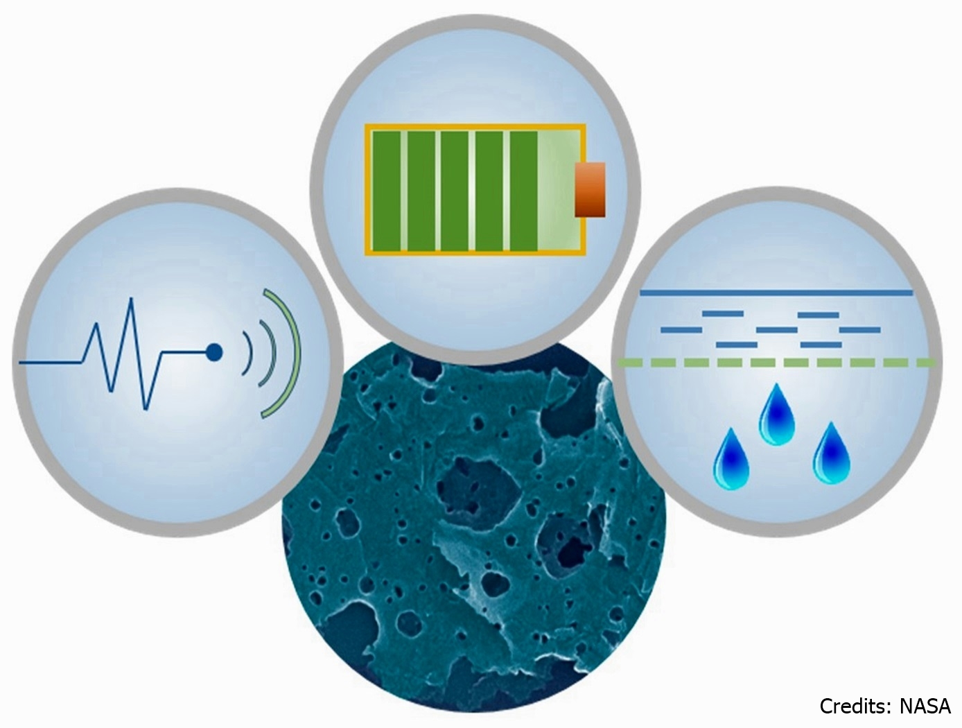
Molecular Adsorber Coating (MAC)
MAC is a zeolite based coating that captures and traps molecules in its microscopically porous structure. This microscopic nano-textured structure, consisting of large open pores or cavities, within a crystal- like structure, provides a large surface area to mass ratio that maximizes available trapping efficiency. MAC is a durable coating that is applied through spray application.
These sprayable coatings eliminate the major drawbacks of puck type adsorbers (weight, size, and mounting hardware requirements), resulting in cost savings, mass savings, easier utilization, greater adsorber surface area, more flexibility, and higher efficiency.
This coating works in air, as well as vacuum systems, depending on the application. There is potential for ground based spin-off applications of this coating, particularly in areas where contaminants and volatile compounds need to be collected and contained. Example industries include: pharmaceutical production, the food industry, electronics manufacturing (circuit boards and wafers), laser manufacturing, vacuum systems, chemical processing, paint booths, and general gas and water adsorption.
Mechanical and Fluid Systems

Fluid Structure Coupling Technology
FSC is a passive technology that can operate in different modes to control vibration:
Harmonic absorber mode: The fluid can be leveraged to act like a classic harmonic absorber to control low-frequency vibrations. This mode leverages already existing system mass to decouple a structural resonance from a discrete frequency forcing function or to provide a highly damped dead zone for responses across a frequency range.
Shell mode: The FSC device can couple itself into the shell mode and act as an additional spring in a series, making the entire system appear dynamically softer and reducing the frequency of the shell mode. This ability to control the mode without having to make changes to the primary structure enables the primary structure to retain its load-carrying capability.
Tuned mass damper mode: A small modification to a geometric feature allows the device to act like an optimized, classic tuned mass damper.
materials and coatings
Holey Carbon Allotropes
This invention is for scalable methods that allows preparation of bulk quantities of holey nanocarbons with holes ranging from a few to over 100 nm in diameter. The first method uses metal particles as a catalyst (silver, copper, e.g.) and offers a wider range of hole diameter. The second method is free of catalysts altogether and offers more rapid processing in a single step with minimal product work-up requirements and does not require solvents, catalysts, flammable gases, additional chemical agents, or electrolysis. The process requires only commercially available materials and standard laboratory equipment; and, it is scalable. Properties that can be controlled include: surface area, pore volume, mechanical properties, electrical conductivity, and thermal conductivity.
mechanical and fluid systems

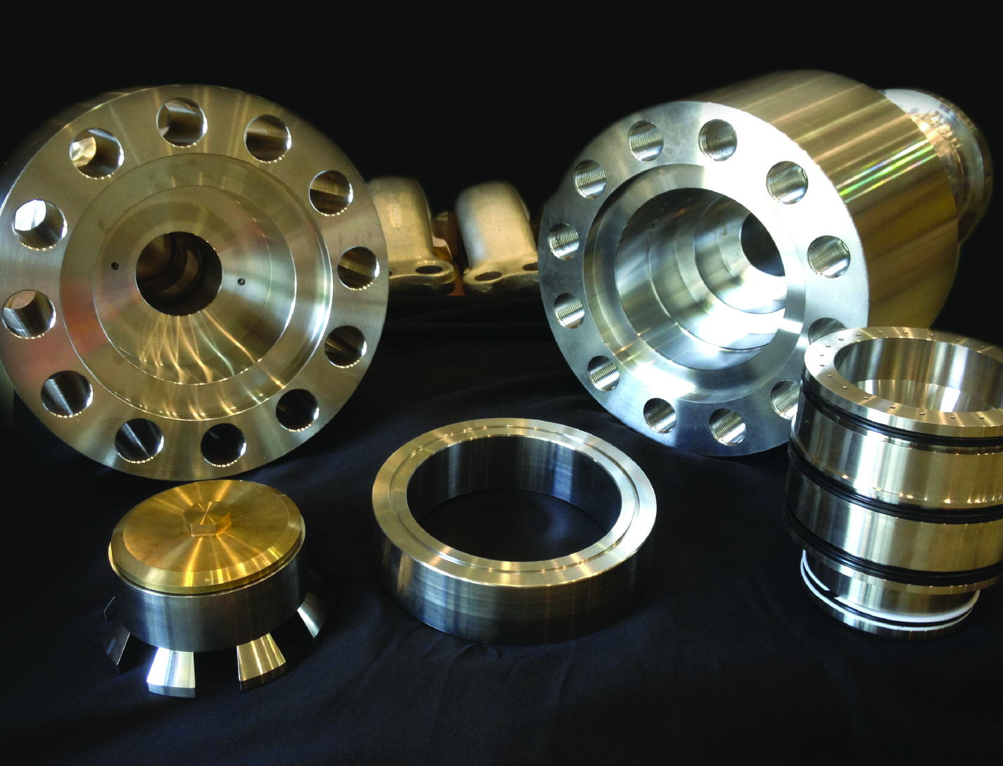
High-Temperature Single Crystal Preloader
For extremely high-temperature sealing applications, Glenn researchers have devised novel methods for fabricating single-crystal preloaders. NASA's high-temperature preloaders consist of investment cast or machined parts that are fabricated in various configurations from single crystal superalloys. Machined preloaders include a variety of spring configurations, compressed axially or radially, fabricated from single crystal slabs. Before machining, the slabs are carefully oriented in a special goniometer using x-diffraction techniques. This helps to maintain proper crystal orientation relative to the machined part and the applied loads. For more complex geometry components which cannot be easily and economically machined, an investment casting approach would be used. Complex preloader geometries include wire coil springs of various configurations. These single crystal preloaders would be designed with the appropriate stiffness for the intended thermal barrier/seal application and placed underneath, or integrated within, the seal/barrier. At extrememly high temperature, the preload device keeps the seal/barrier mated against the opposing surface as the gap between the two surfaces changes, maintaining contact between surfaces and preventing convective heat transfer.
Communications

Real-Time Tracking System
The innovation builds upon conventional UWB hardware by incorporating tracking methodology and algorithms in addition to external amplifiers for signal boost. The tracking methodology is a triangulation calculation consisting of Angle of Arrival (AOA) and Time Difference of Arrival (TDOA) using a cross-correlation peak detection method. By directly estimating TDOA information from UWB pulses, the method achieves the high temporal resolution (on the order of picoseconds) needed to measure AOA with extreme precision. The system uses a PC to synchronize and process data in real time from two receivers, or clusters, to display the position of the transmitter-equipped person or object. The interface software enables the PC to access the two data sets simultaneously through separate sockets. In the data collection process, data segments from each receiver are interleaved with those from the other receiver in chronological order of collection. Within the PC, the data segments are stored in a separate buffer; therefore, the contents of the buffers are representations of the same UWB pulse waveform arriving at the two receivers at approximately the same time. This data synchronization provides the separate and simultaneous collection of waveform data that the tracking algorithm requires for accurate real-time tracking.
mechanical and fluid systems
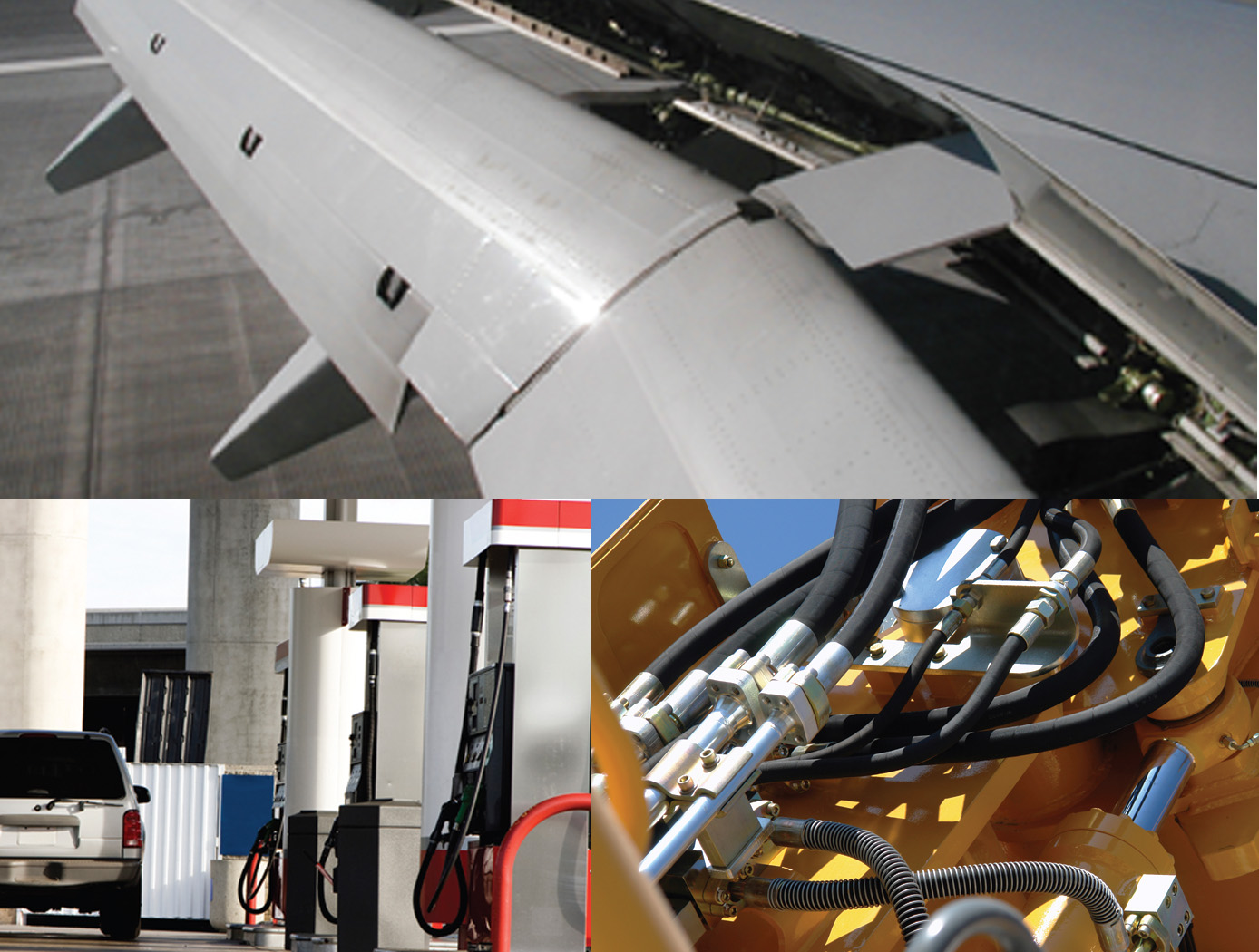
Floating Piston Valve
Instead of looking to improve current valve designs, a new type of valve was conceived that not only addresses recurring failures but could operate at very high pressures and flow rates, while maintaining high reliability and longevity. The valve design is applicable for pressures ranging from 15-15,000+ psi, and incorporates a floating piston design, used for controlling a flow of a pressurized working fluid.
The balanced, floating piston valve design has a wide range of potential applications in all sizes and pressure ranges. The extremely simple design and few parts makes the design inherently reliable, simple to manufacture, and easy to maintain. The valve concept works with soft or hard metal seats, and the closing force is easily adjustable so that any closing force desired can be created. The fact that no adjustment is required in the design, ensures valve performance throughout valve life and operation.
This valve has many unique features and design advantages over conventional valve concepts:
- The largest advantage is the elimination of the valve stem and any conventional actuator, reduces physical size and cost.
- It is constructed with only 5 parts.
- It eliminates the need for many seals, which reduces failure, downtime and maintenance while increasing reliability and seat life.
- The flow path is always axially and radially symmetric, eliminating almost all of the flow induced thrust loads - even during transition from closed to open.
Sensors
Fluid Measurement Sensor
The fluid measurement sensor is configured with a spiral electrical trace on flexible substrate. The sensor receives a signal from the accompanying magnetic field data acquisition system. Once electrically active, the sensor produces its own harmonic magnetic field as the inductor stores and releases magnetic energy. The antenna of the measurement acquisition system is switched from transmitting to receiving mode to acquire the magnetic-field response of the sensor. The magnetic-field response attributes of frequency, amplitude, and bandwidth of the inductor correspond to the physical property states measured by the sensor. The received response is correlated to calibrated data to determine the physical property measurement. When multiple sensors are inductively coupled, the data acquisition system only needs to activate and read one sensor to obtain measurement data from all of them.
Fluid level measurement occurs in several ways. In the immersion method, the capacitance of the sensor circuit changes as it is immersed in fluid, thus changing the frequency response as the fluid level rises or falls. Fluid level can also be measured from the outside of a non-conductive container. The response frequency from the sensor is dependent upon the inductance of the container plus the combination of fluid and air inside it, which corresponds to the level of liquid inside the container. Roll and pitch are measured by using three or more sensors in a container. With any given orientation, each sensor will detect a different fluid level, thus providing the basis for calculating the fluid angle. Volume can be measured in the same way, using the angle
levels detected by the sensors and the geometric characteristics of the container to perform the volume calculation.

