Search
robotics automation and control
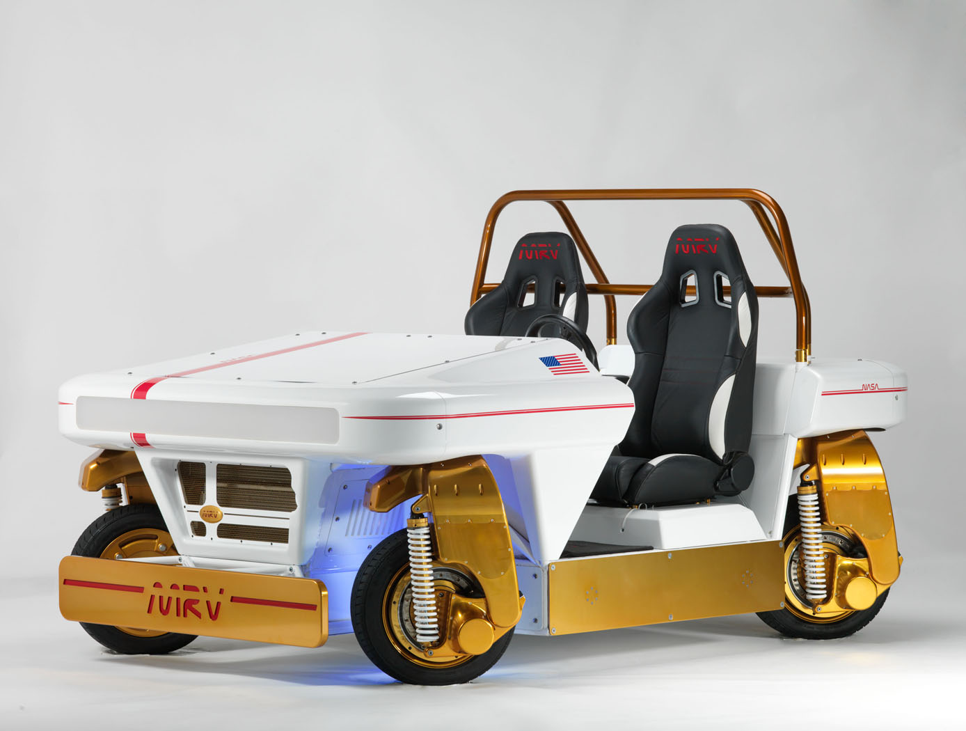
Modular Robotic Vehicle (MRV)
The Modular Robotic Vehicle (MRV) is a vehicle designed for transportation in congested areas. The MRV is relatively small, easy to maneuver and park. The MRV was designed without a central power plant, transmission, fuel tank, and direct mechanical linkages between driver input devices and the actuators used to accelerate, brake and/or steer the car. These core vehicle functions are located at the corners of the vehicle in a modular electric corner assembly or eCorner. Because the MRV uses a by-wire control system, substantial space and weight is conserved compared to conventional designs. Moreover, the functional capabilities that are provided by the individual eCorners enable control of the vehicle in a variety of different operating modes.
The eCorners provide significant flexibility in driving options. For example, the driving mode can be switched so that all four wheels point and move in the same direction achieving an omni-directional motion or all wheels can be pointed perpendicular to the center of the vehicle allowing rotation around its center axis. This mode makes some driving maneuvers like parallel parking as easy as driving next to the spot, turning the wheels 90 degrees, and driving into the open spot in a sideways motion. Each eCorner includes its own redundancy to protect for electrical failures within the systems. The driver can choose to control the vehicle with a conventional steering wheel or add inputs through a multi-axis joystick for additional control in some of the more advanced drive modes. The vehicle has the propulsion motors located inside of each eCorner with the capability of producing 190 ft-lbs of torque with a current top speed of 40 mph. An active thermal control loop maintains the temperatures of these high powered motors and a separate thermal loop cools the avionics and the custom lithium-ion battery packs. The linked vehicles are able to exchange or share control data and electrical power. Finally, the MRV has remote driving control capability.
instrumentation

RFID-Enabled Wireless Instrumentation
With a form factor close to a deck of playing cards, the system interrogator has custom software to interface with and service a population of sensor tags at the required data rates. Each EPCglobal C1G2 sensor tag uses incident interrogator energy to charge its small integrated circuit (IC), which reads an internal memory bank, encodes identification data, and uses that information to modulate and backscatter a reply to the interrogator using reflected interrogator energy. Two tag interfaces allow the attached processor to power the reading/writing of data to the tag memory and then allows the interrogator to power the reading of the tag memory data. When neither of the two interfaces are engaged, the RFID IC is completely powered down. Reading and writing tag memory consumes relatively little power compared to the power draw of active transmitter/receiver protocols like Bluetooth, Zigbee, and Wi-Fi. Compared to passive sensing protocols, this wireless instrumentation system enables sampling of a larger population of tags without the computational burden associated with surface acoustic wave (SAW) sensing. RFID-Enabled Wireless Instrumentation technology allows the RFID interrogator to write data through the interface of a sensor tag memory bank using only interrogator power. With only minimal cost to the sensors power budget, the microcontroller unit can read that data out over the serial interface. The sensor can transmit and receive data at no effective cost to its small coin cell battery power supply.
This technology is readiness level (TRL) 8 (actual system completed and "flight qualified" through test and demonstration) and the innovation is now available for your company to license. Please note that NASA does not manufacture products itself for commercial sale.
Aerospace
Aerospace Vehicle Entry Flightpath Control
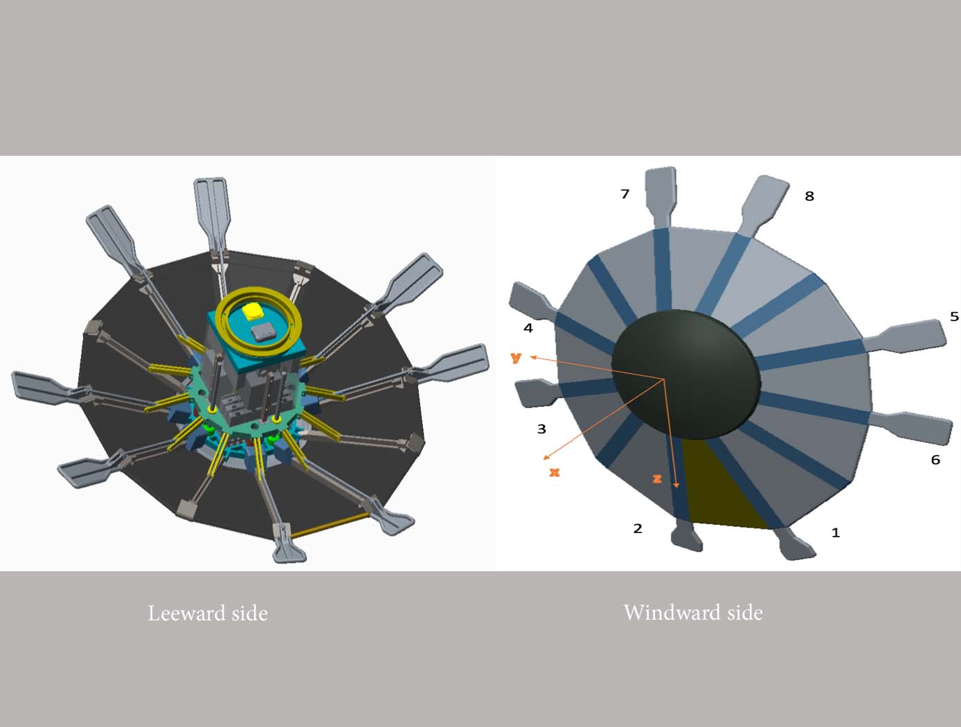
This novel flightpath control system exploits the dihedral effect to control the bank angle of the vehicle by modulating sideslip (Figure 1). Exploiting the dihedral effect, in combination with significant aerodynamic forces, enables faster bank accelerations than could be practically achieved through typical control strategies, enhancing vehicle maneuverability. This approach enables vehicle designs with fewer control actuators since roll-specific actuators are not required to regulate bank angle. The proposed control method has been studied with three actuator systems (figure below), Flaps Control System (FCS); Mass Movement Control System (MMCS); and Reaction Control System (RCS).
• FCS consists of a flap configuration with longitudinal flaps for independent pitch control, and lateral flaps generating yaw moments. The flaps are mounted to the shoulder of the vehicle’s deployable rib structure. Additionally, the flaps are commanded and controlled to rotate into or out of the flow. This creates changes in the vehicle’s aerodynamics to maneuver the vehicle without the use of thrusters.
• MMCS consists of moveable masses that are mounted to several ribs of the DEV heatshield, steering the vehicle by shifting the vehicle’s Center of Mass (CoM). Shifting the vehicle’s CoM adjusts the moment arms of the forces on the vehicle and changes the pitch and yaw moments to control the vehicle’s flightpath.
• RCS thrusters are mounted to four ribs of the open-back DEV heatshield structure to provide efficient bank angle control of the vehicle by changing the vehicle’s roll. Combining rib-mounted RCS thrusters with a Deployable Entry Vehicle (DEV) is expected to provide greater downmass capability than a rigid capsule sized for the same launch
Mechanical and Fluid Systems
Active Flow Control System for Simple-hinged Flaps
Although simple-hinged flaps represent optimal high-lift systems for reducing cruise drag, previous attempts to design flow control systems enabling such technology in transport aircraft have been unsuccessful. This is largely because such systems generally require a tradeoff between (a) the ability to achieve the required lift performance, and (b) possessing sufficiently low pneumatic power to enable feasible aircraft system integration (i.e., avoiding excess weight penalties associated with high pneumatic power). For example, electrically powered AFC systems (e.g., plasma actuators, synthetic jet actuators) have practical power requirements, but with limited control authority, making such systems ineffective for highly deflected flaps. On the other hand, circulation control systems can provide necessary lift for airfoils or wings with high flap deflections, but require too much pneumatic power for aircraft integration. NASA’s HELP AFC system represents a breakthrough in flow separation control technology – to efficiently achieve necessary lift performances while requiring low pneumatic power relative to alternative flow control techniques.
NASA’s HELP AFC system uses a unique two-row actuator approach comprised of upstream sweeping jet (SWJ) actuators and downstream discrete jets, which share the same air supply plenum. The upstream (row 1) SWJ actuators provide good spanwise flow-control coverage with relatively mass flow, effectively pre-conditioning the boundary layer such that the downstream (row 2) discrete jets achieve better flow control authority. The two row actuator system, working together, produce a total aerodynamic lift greater than the sum of each row acting individually. The result is a system that generates sufficient lift performance for simple-hinged flaps with pneumatic power requirements low enough to enable aircraft integration.
Communications
Conformal, Lightweight, Aerogel-Based Antenna
This CLAS-ACT is a lightweight, active phased array conformal antenna comprised of a thin multilayer microwave printed circuit board built on a flexible aerogel substrate using new methods of bonding. The aerogel substrate enables the antenna to be fitted onto curved surface. NASA's prototype operates at 11-15 GHz (Ku-band), but the design could be scaled to operate in the Ka-band (26 to 40 GHz).
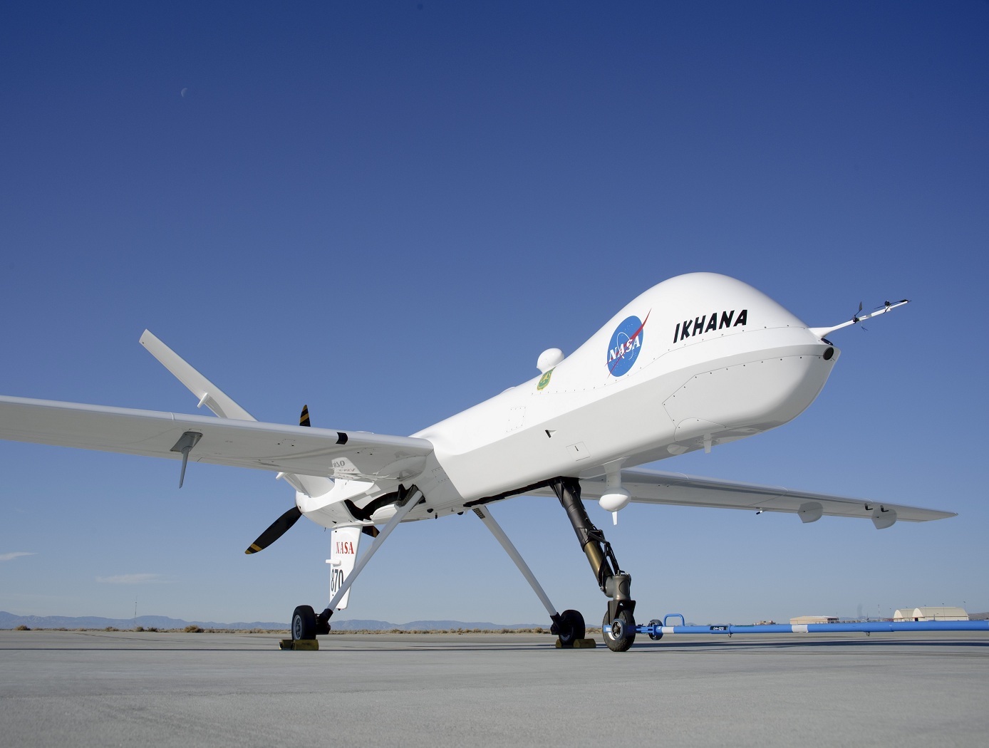
The antenna element design incorporates a dual stacked patch for wide bandwidth to operate on both the uplink and downlink frequencies with a common aperture. These elements are supported by a flexible variant of aerogel that allows the material to be thick in comparison to the wavelength of the signal with little to no additional weight. The conformal antenna offers advantages of better aerodynamics for the airframe, and potentially offers more physical area to either broadcast further distances or to broadcast at a higher data rate. The intended application for this antenna is for UAVs that need more than line of sight communications for command and control but cannot accommodate a large satellite dish. Examples may be UAVs intended for coastal monitoring, power line monitoring, emergency response, and border security where remote flying over large areas may be expected. Smaller UAVs may benefit greatly from the conformal antenna. Another possible application is a UAV mobile platform for Ku-band satellite communication.
With the expectation that 5G will utilize microwave frequencies this technology may be of interest to other markets outside of satellite communications. For example, the automotive industry could benefit from a light weight conformal phased array for embedded radar. Also, the CLAS-ACT could be used for vehicle communications or even vehicle to vehicle communications.
Aerospace

Method And System for Enhancing Vehicle Performance and Design Using Parametric Modeling and Gradient-Based Control Integration
The parametric modeling system allows for the integrated design and optimization of aerospace vehicles by unifying physical and control subsystems within a single computational model. The system includes representations of the vehicle’s geometry, structural load, propulsion, energy storage, and GNC systems. The system performs sensitivity analysis on key performance metrics (e.g., fuel consumption, heat load, and mechanical forces) to determine how changes in design parameters affect overall performance. By incorporating real-world conditions, such as wind variations and sensor noise, the system allows for the use of real-time feedback to refine vehicle designs. The optimization process uses a gradient-based algorithm to iteratively adjust parameters so that constraints such as structural integrity, thermal protection, and fuel capacity are met. The system generates a Pareto front representing trade-offs between performance metrics that allow engineers to visualize optimal designs for different mission profiles, which enhances design accuracy while reducing the need for expensive physical testing.
Aerospace
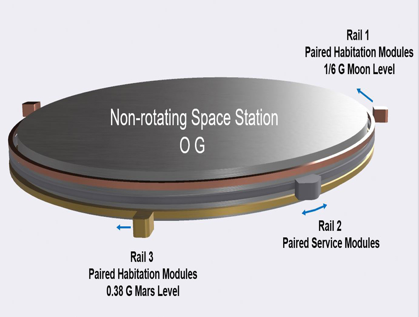
Spacecraft with Artificial Gravity Modules
Conventionally, the approaches of creating artificial gravity in space was envisioned as a large rotating space station that creates an inertial force that mimics the effects of a gravitational force. However, generating artificial gravity with large rotating structures poses problems, including (1) the need to mass balance the entire rotating spacecraft in order to eliminate or minimize rotational imbalance causing gyroscopic precession/nutation motions and other oscillations of the rotating spacecraft; (2) the potentially prohibitive cost, time and schedule to build such a large rotating system; (3) the need to mass balance the spacecraft in real-time so as to minimize passenger discomfort and structural stress on the spacecraft; (4) the difficulty in docking other spacecraft to the rotating spacecraft; (5) the absence or minimal presence of non-rotating structure for 0G research and industrial use; and (6) the generation of extraneous Coriolis effect on spacecraft inhabitants. The novel technology can help solve the problems referenced above and other problems by (1) providing a non-rotating space station or structure, and connecting modules that generate artificial gravity by traveling along a circular path around the non-rotating space station; (2) providing modules that are more easily built and balanced; (3) providing a stationary structure that can provide a platform for other components that do not need gravity to function; (4) providing capability to actively interrogate what levels of mass imbalance are acceptable, for use in determining operational constraints; and (5) reducing or eliminating Coriolis effect on occupants in habitation modules. The concepts of the invention are very cost-effective and allow for building a minimal initial system to produce artificial gravity at the first phases of construction, before the full structure is built. An additional benefit is that construction and assembly of new capabilities can be performed without disrupting the ongoing artificial gravity environment of the existing structure.
Electrical and Electronics

Enhanced DC Bus Emulator
Combining a dynamic load emulation technique with a PWM dithering technique, NASA’s technology provides a more efficient, cost-effective, and practical method to emulate complex loads. While there are commercially available electronic device loads on the market that meet basic emulation needs, these devices are limited; they are limited with respect to small input voltage changes, and to feedback signals from the device’s power system, which may lack the strength and resolution needed to emulate accurately.
A common solution for the bus emulation limitation is to construct a model of an actual microgrid using representative loads and connections. But this can be complex, costly, and have limitations in performance. NASA’s approach addresses these challenges without creating an actual model microgrid to replicate the systems.
As opposed to stand-alone COTS electronic load devices or model microgrids using representative loads and connections for a given test, NASA’s technology is a system constructed of an input power filter, a COTS electronic load device or load subsystem, and a power control circuit. The input power filter is designed to emulate load or bus performance at the medium to high frequency range. The power control circuit combined with the electronic load or load subsystem emulates lower frequency and constant power dynamics of the system. Lastly, the power control circuit linearizes digitization and quantization issues present with digitally controlled COTS electronic loads.
The power control circuit can be set to measure a load voltage, which is divided by a determined value for power, and combined with a triangle wave dither (the power control circuit block image demonstrates how to integrate a triangle wave dither). This dither dynamically adjusts the electrical current or power to keep it constant within the commercially purchased load device, enabling accurate emulation of complex DC microgrid systems.
Aerospace

Multistage Free-Flight Testing System
The disclosed technology provides a multistage system for evaluating the free-flight behavior of test articles across of the supersonic, transonic, and subsonic regimes. First, a drop platform is lifted to high altitudes using a lifting device, such as a stratospheric balloon. The drop platform houses multiple projectiles, each containing an ejection mechanism, an on-board avionics suit, and an instrumented test article. Upon reaching the target altitude via the lifting device, the drop platform releases the projectiles sequentially. Each projectile accelerates to a target speed and altitude before ejecting its test article into the freestream. The test articles, such as a scaled re-entry capsule, then collect flight data during their descent through the various Mach regimes, providing valuable insights into their flight performance under mission-relevant conditions.
This innovative testing system offers several benefits. It enables the simultaneous testing of multiple vehicles, facilitating the evaluation of design variations as well as statistical analyses of vehicle behavior. This system also provides significant cost savings in comparison to other state-of-the-art testing methods, such as ballistic range testing. Additionally, the test articles within each projectile are easily interchangeable through a simple, modular change of a support surface in the ejection mechanism. This flexibility enables the system to accommodate a range of other aerodynamic technologies, including other vehicles, parachutes, propulsion systems, and defense technologies. This system can enhance the efficiency and robustness of reentry vehicle design, testing, and simulation operations through the collection of rich, flight-relevant data.
Information Technology and Software

Computer Vision Lends Precision to Robotic Grappling
The goal of this computer vision software is to take the guesswork out of grapple operations aboard the ISS by providing a robotic arm operator with real-time pose estimation of the grapple fixtures relative to the robotic arm’s end effectors. To solve this Perspective-n-Point challenge, the software uses computer vision algorithms to determine alignment solutions between the position of the camera eyepoint with the position of the end effector – as the borescope camera sensors are typically located several centimeters from their respective end effector grasping mechanisms.
The software includes a machine learning component that uses a trained Region-based Convolutional Neural Network (R-CNN) to provide the capability to analyze a live camera feed to determine ISS fixture targets a robotic arm operator can interact with on orbit. This feature is intended to increase the grappling operational range of ISS’s main robotic arm from a previous maximum of 0.5 meters for certain target types, to greater than 1.5 meters, while significantly reducing computation times for grasping operations.
Industrial automation and robotics applications that rely on computer vision solutions may find value in this software’s capabilities. A wide range of emerging terrestrial robotic applications, outside of controlled environments, may also find value in the dynamic object recognition and state determination capabilities of this technology as successfully demonstrated by NASA on-orbit.
This computer vision software is at a technology readiness level (TRL) 6, (system/sub-system model or prototype demonstration in an operational environment.), and the software is now available to license. Please note that NASA does not manufacture products itself for commercial sale.

