Search
PATENT PORTFOLIO

Spacecraft to Remove Orbital Debris
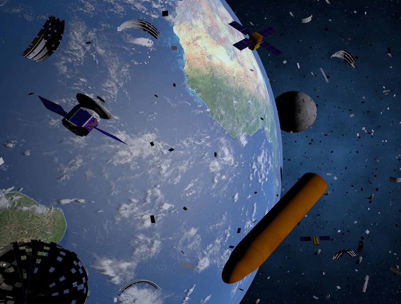
An approach to mitigating the creation of additional orbital debris is to remove the sources of future medium debris by actively removing large spent objects from congested orbits. NASA has introduced the ADRV, an efficient and effective solution to remove large debris from LEO such as spent rocket bodies and non-functional satellites. The concept yields a single use, low-cost, lightweight, high mass fraction vehicle that enables the specific removal of large orbital debris (1000 - 4000 kg mass, 200 - 2000 km altitude, and 20 – 98-degree inclination). The ADRV performs rendezvous, approach, and capture of non-cooperative tumbling debris objects, maneuvering of the mated vehicle, and controlled, targeted reposition or deorbit of the mated vehicle. Due to its small form factor, up to eight ADRVs can be launched in a single payload, enabling high impact orbital debris removal missions within the same inclination group.
Three key technologies were developed to enable the ADRV: - 1) The spacecraft control system (SCS) is a guidance, navigation, and control system that provides vehicle control during all phases of a mission; - (2) The debris object characterization system (DOCS) characterizes movement and capture of non-cooperative targets; and - (3) The capture and release system (CARS) allows the vehicle to capture and mate with orbital debris targets. These technologies can improve the current state-of-the-art capabilities of automated rendezvous and docking technology significantly for debris objects with tumbling rates up to 25 degrees per second. This approach leverages decades of spaceflight experience while automating key mission areas to reduce cost and improve the likelihood of success.

Computer Vision Lends Precision to Robotic Grappling
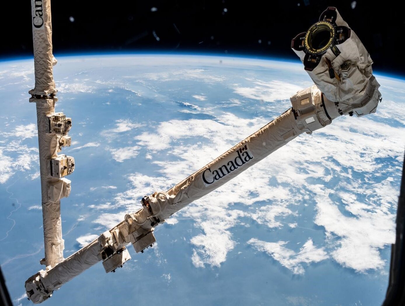
The goal of this computer vision software is to take the guesswork out of grapple operations aboard the ISS by providing a robotic arm operator with real-time pose estimation of the grapple fixtures relative to the robotic arms end effectors. To solve this Perspective-n-Point challenge, the software uses computer vision algorithms to determine alignment solutions between the position of the camera eyepoint with the position of the end effector as the borescope camera sensors are typically located several centimeters from their respective end effector grasping mechanisms.
The software includes a machine learning component that uses a trained regional Convolutional Neural Network (r-CNN) to provide the capability to analyze a live camera feed to determine ISS fixture targets a robotic arm operator can interact with on orbit. This feature is intended to increase the grappling operational range of ISSs main robotic arm from a previous maximum of 0.5 meters for certain target types, to greater than 1.5 meters, while significantly reducing computation times for grasping operations.
Industrial automation and robotics applications that rely on computer vision solutions may find value in this softwares capabilities. A wide range of emerging terrestrial robotic applications, outside of controlled environments, may also find value in the dynamic object recognition and state determination capabilities of this technology as successfully demonstrated by NASA on-orbit.
This computer vision software is at a technology readiness level (TRL) 6, (system/sub-system model or prototype demonstration in an operational environment.), and the software is now available to license. Please note that NASA does not manufacture products itself for commercial sale.

Battery Management System
The technology is comprised of a simple and reliable circuit that detects a single bad cell within a battery pack of hundreds of cells and it can monitor and balance the charge of individual cells in series. NASA's BMS is cost effective and can enhance safety and extend the life of critical battery systems, including high-voltage Li-ion batteries that are used in electric vehicles and other next-generation renewable energy applications.
The BMS uses saturating transformers in a matrix arrangement to monitor cell voltage and balance the charge of individual battery cells that are in series within a battery string. The system includes a monitoring array and a voltage sensing and balancing system that integrates simply and efficiently with the battery cell array, limiting the number of pins and the complexity of circuitry in the battery. The arrangement has inherent galvanic isolation, low cell leakage currents, and allows a single bad or imbalanced cell in a series of several hundred to be identified. Cell balancing in multi-cell battery strings compensates for weaker cells by equalizing the charge on all the cells in the chain, thus extending battery life. Voltage sensing helps avoid damage from over-voltage that can occur during charging and from under-voltage that can occur through excessive discharging.

Robotic System for Infra-structure Reconnaissance
The robotic system is comprised of six main components: the orb that performs the reconnaissance, an orb injector housing that attaches to a piping network, a tether and reel subsystem that attaches to the back of the injector housing, a fluid injection subsystem that attaches toward the front of the injector housing, an external power and data subsystem, and associated control and monitoring software.
Usage of the system begins with an operator attaching the injector housing, with the orb stowed inside, to a flanged gate valve belonging to the piping network of concern. Requisite power, data, and fluid subsystems are attached, and the system is energized for usage. The orb is released via the tether and reel, and a controlled fluid force is imparted on the orb to help guide it along its mission. The tether supplies power and guidance to the orb, and relays real-time data back to the operator.
The orb’s interior features a modular plug-and-play architecture which may comprise COTS instrumentation for reconnaissance or investiga-tion, LIDAR, and inertial measuring and motion sensors. This instru-mentation could be used in combination with other sub-systems such as lighting, and core and sample retrieving mechanisms. These com-ponents are supported by other onboard devices such as a CPU, power source and controller, and data transmission encoders and multiplexers.
The Robotic System for Infrastructure Reconnaissance is at TRL 8 (actual system completed and "flight qualified" through test and demonstration), and is now available for licensing. Please note that NASA does not manufacture products itself for commercial sale.

ThermoArc Facilitates Low-Cost Li-Ion Battery Testing
For years, NASA and the battery industry have been improving passive propagation resistant (PPR) Li-ion battery cell technology by enhancing their material and design choices. These efforts help ensure that a single cell’s TR event does not overheat adjacent cells or the entire battery pack ultimately causing fire or explosion. To improve cell integrity, single cells within battery packs are triggered into TR so that the battery pack can be analyzed for its TR resistance.
ThermoArc operates by initiating a plasma arc, capable of delivering thermal energy up to 100W, to a very small (1mm diameter) section of the cell. The extremely localized high heat flux rapidly degrades a small section of the internal cell separator, resulting in a short circuit that leads to TR. This technology comprises several components: a high-turn-ratio step-up transformer capable of producing a minimum of 1,000 V upon the secondary winding, an H-bridge electronic circuit to drive the transformer on the primary side, two tungsten electrodes to deliver the plasma arc, and a power supply unit.
ThermoArc applications may exist in any Li-ion battery cell/pack testing application where TR must be induced in an individual cell. Such applications could include testing of PPR battery packs to ensure single cell runaway does not cause catastrophic damage, more general battery destructive testing designed to better understand battery failure states, or other experimental testing. Companies interested in licensing this innovation may include those that manufacture internal short-circuit (ISC) cells or other devices used to induce TR at the individual cell level, battery testing firms, and Li-ion battery manufacturers with a focus on Li-ion battery packs for critical applications.
ThermoArc is at a technology readiness level (TRL) 5 (component and/or breadboard validation in laboratory environment) and is now available for patent licensing. Please note that NASA does not manufacture products itself for commercial sale.

ARC ANGEL Reduces Gravity’s Effect on Arms
ARC ANGEL is an active robotic system like ARGOS; however, its electric motor is not mounted overhead to a runway and bridge system, but instead is mounted to the test subject’s backpack-like PLSS where the motor(s) supplies real-time actuation torque off-loading to the upper arms via cabling. If a test subject picks-up a hammer, the system will react immediately to offload the weight of the hammer relative to the programmed environment.
The ARC ANGEL system is comprised of an electric motor(s), soft goods, electronics hardware, firmware, and software. To provide a smoothly operating arm offloading analog and optimize system performance, engineers at JSC coded software that leverages kinematic algorithms and closed-loop architecture for motor control, along with custom computer language scripts to ingest sensor data. This allows ARC ANGEL’s subsystems to be seamlessly integrated and accurately simulate one to zero G environments.
During operation, compact tension sensors and inertial measurement units detect arm weight and motion and provide a closed-loop control system that feeds data to a single-board computer and requisite firmware for processing. A custom graphical user interface was also developed in-house to provide controls for inputting desired arm offload values. Additionally, ARC ANGEL features its own power supply that provides power to its subcomponents without external cables. This allows the ability to function independently from ARGOS and further lends itself to potential terrestrial applications.
This work directly correlates to active exosuit development that is being implemented for rehabilitation and/or assistive medical devices. ARC ANGEL is essentially providing a desired assistance (offload) while maintaining a subject’s full range of motion. The system hardware and software can be modified to custom-fit an individual without a spacesuit and toward limb-assisted movement – not just arm offloading. ARC ANGEL may already meet a higher physical demand and robustness given that it is engineered to perform in challenging environments with greater loads.
ARC ANGEL is at a technology readiness level (TRL) 5 (component and/or breadboard validation in laboratory environment) and is now available for patent licensing. Please note that NASA does not manufacture products itself for commercial sale.

Robo-Glove
Originally developed by NASA and GM, the Robo-Glove technology was a spinoff of the Robonaut 2 (R2), the first humanoid robot in space. This wearable device allows the user to tightly grip tools and other items for longer periods of time without experiencing muscle discomfort or strain. An astronaut working in a pressurized suit outside the space station or an assembly operator in a factory might need to use 15 to 20 lbs of force to hold a tool during an operation. Use of the Robo-Glove, however, would potentially reduce the applied force to only 5 to 10 lbs.
The Robo-Glove is a self-contained unit, essentially a robot on your hand, with actuators embedded into the glove that provide grasping support to human fingers. The pressure sensors, similar to the sensors that give R2 its sense of touch, are incorporated into the fingertips of the glove to detect when the user is grasping an object. When the user grasps the object, the synthetic tendons automatically retract, pulling the fingers into a gripping position and holding them there until the sensor is released by releasing the object. The current prototype weighs around two pounds, including control electronics and a small display for programming and diagnostics. A lithium-ion battery, such as one for power tools, is used to power the system and is worn separately on the belt.

Space Suit RoboGlove (SSRG)
NASA is currently developing the next generation space suit for future missions, including the optimization of space suit gloves. When non-assisted space suit gloves are coupled to a pressurized suit and operated in a vacuum, they tend to limit the range of motion of an astronaut's hand to as little as 20% of normal range. Many of NASA's future missions will be in challenging environments where an astronaut’s hand dexterity will be critical for the success of NASA missions. Innovators at JSC have improved the performance on the second-generation, robotically assisted SSRG, to reduce exertion and improve the hand strength and dexterity of an astronaut in situ.
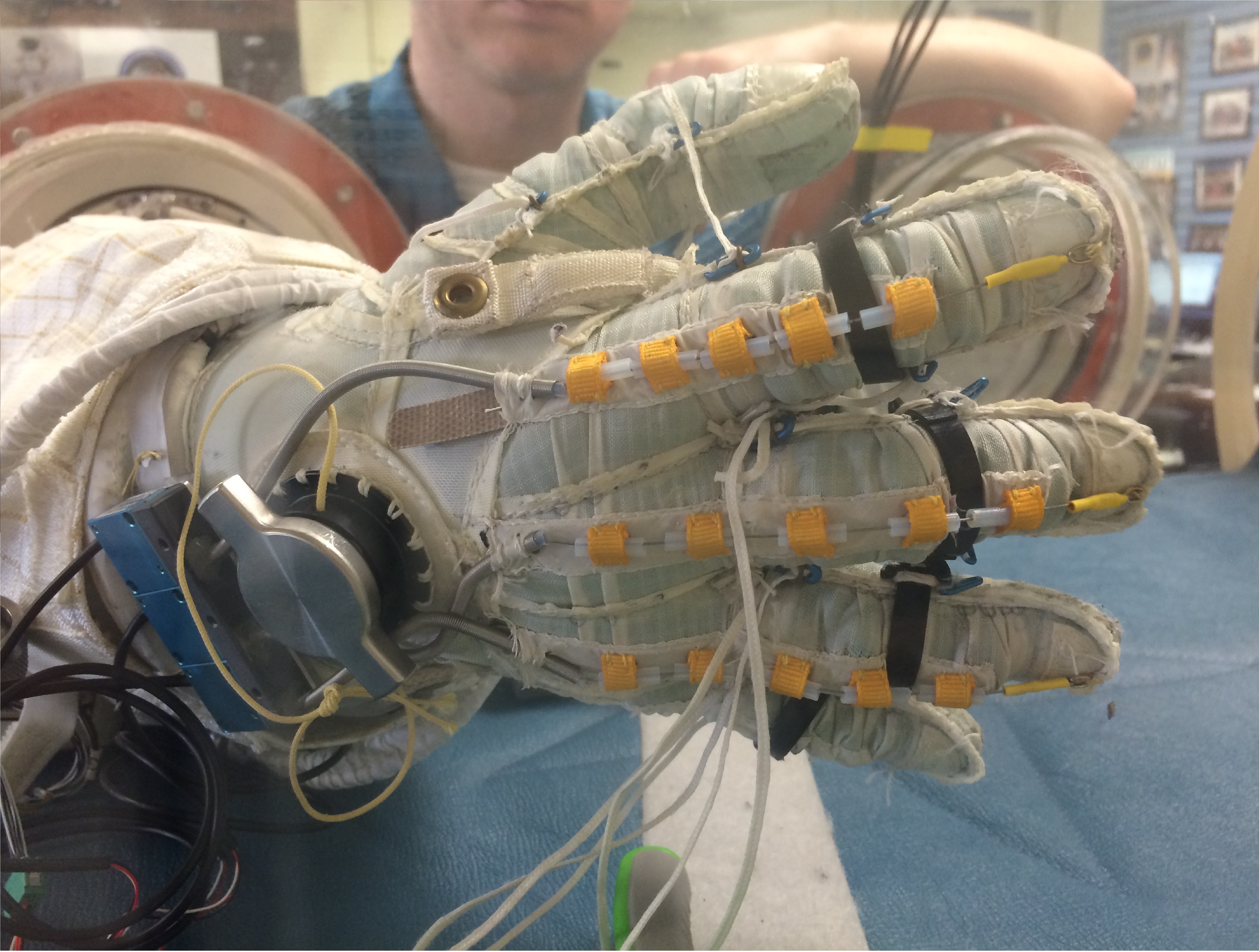
The SSRG’s system detects user finger movements using string potentiometers and contact with objects using force-sensitive resistors (FSRs). FSRs are imbedded in the distal and medial phalanges, palmar side of the glove. To move a finger, an actuator pulls a tendon through a Bowden Cable system which transfers mechanical pulling force of an inner cable relative to a hollow outer cable, like the brakes on a bicycle, as seen in the Figure below. An improved controller commands the new, more powerful linear actuator to drive tendon operation while minding custom controller parameters inputted through a digital editor tool.
The Space Suit RoboGlove is at TRL 6 (system/subsystem model or prototype demonstrated in a relevant environment) and it is now available for licensing. Please note that NASA does not manufacture products itself for commercial sale.

Anonymous Feature Processing for Enhanced Navigation
This concept presents a new statistical likelihood function and Bayesian analysis update for non-standard measurement types that rely on associations between observed and cataloged features. These measurement types inherently contain non-standard errors that standard techniques, such as the Kalman filter, make no effort to model, and this mismodeling can lead to filter instability and degraded performance.
Vision-based navigation methods utilizing the Kalman filter involve a preprocessing step to identify features within an image by referencing a known catalog. However, errors in this pre-processing can cause navigation failures. AFP offers a new approach, processing points generated by features themselves without requiring identification. Points such as range or bearing are directly processed by AFP.
Operating on finite set statistics principles, AFP treats data as sets rather than individual features. This enables simultaneous tracking of multiple targets without feature labeling. Unlike the sequential processing of the Kalman filter, AFP processes updates in parallel, independently scoring each output based on rigorous mathematical functions. This parallel processing ensures robust navigation updates in dynamic environments, and without requiring an identification algorithm upstream of the filter.
Computational simulations conducted at Johnson Space Center demonstrate that AFP's performance matches or exceeds that of the ideal Kalman filter, even under non-ideal conditions. Anonymous Feature Processing for Enhanced Navigation is at a technology readiness level (TRL) 4 (component and/or breadboard validation in laboratory environment) and is now available for patent licensing. Please note that NASA does not manufacture products itself for commercial sale.
View more patents


