Search
aerospace
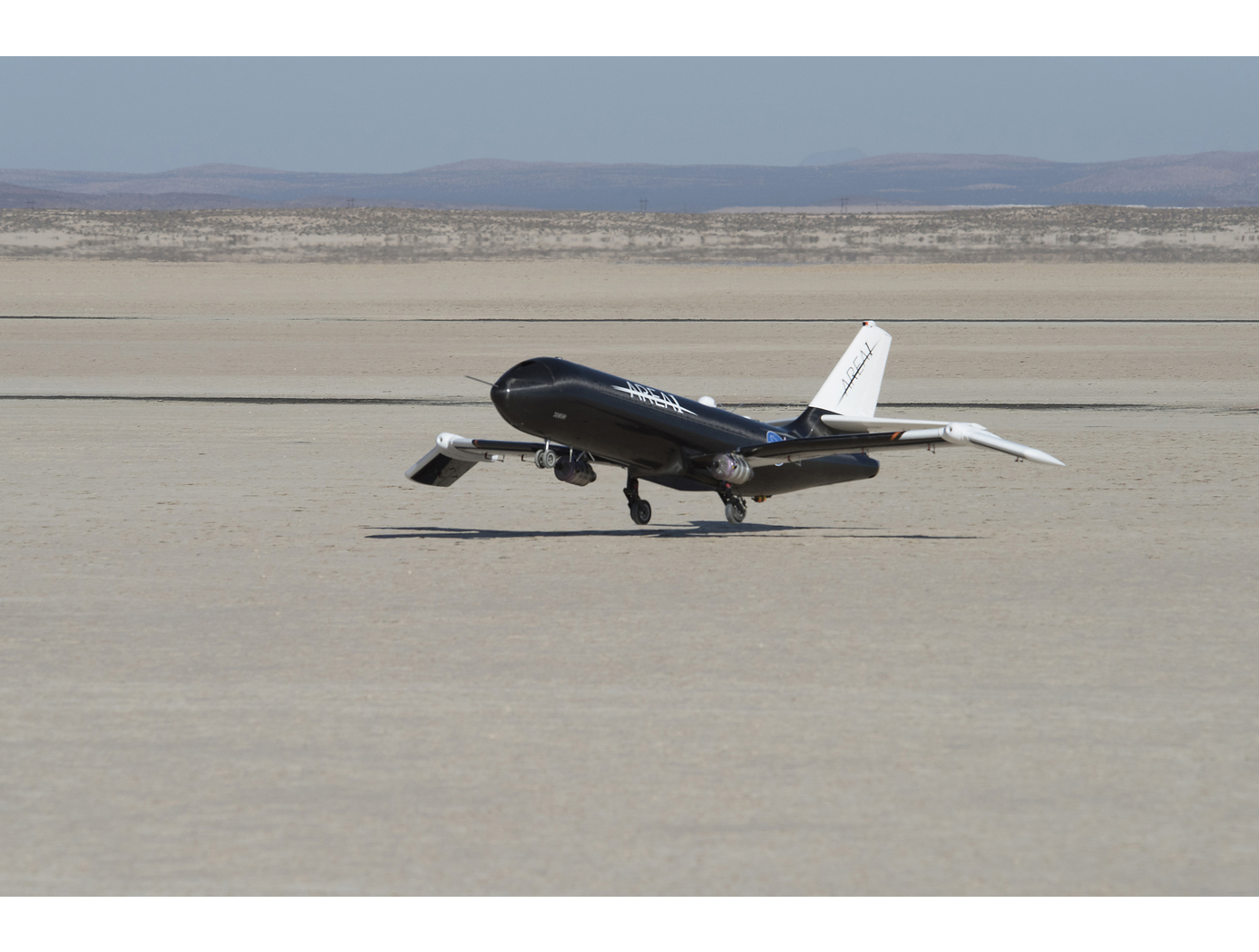
Outer Aileron Yaw Damper
Rudders have long served as the primary flight control surface as is pertains to aircraft yaw. Breaking this mold, NASA's SAW technology is a game-changing development in aircraft wing engineering that reduces rudder motion required to control aircraft. The benefits of reduced rudder dependency led NASA to develop the outer aileron yaw damper to further decrease or eliminate rudder dependency for aircraft using SAWs.
As mentioned, SAWs use shape memory alloy actuators to articulate the outer portion of the wing, effectively creating a movable wingtip. NASA's invention uses an outer aileron located on the wingtips, which is driven (along with the inner ailerons) by a novel control algorithm. The control algorithm, taking into account the wingtip positions, manipulates the outer ailerons to achieve the desired yaw rate. At the same time, it positions the inner ailerons to counter roll rate resulting from the outer aileron. In other words, the control algorithm calculates a control surface ratio (i.e., position of inboard aileron and outboard aileron) that produces desired yaw and roll accelerations.
The system can also be used to offset the existing rudder in current or future aircraft designs. A second part of NASAs novel outer aileron control algorithm modifies the aircrafts rudder loop gain in proportion to outer aileron usage. This allows the outer ailerons and rudder to work in tandem, while at the same time reducing rudder usage.
As a result of this NASA invention, required rudder usage can be reduced or eliminated for aircraft with SAWs. Consequently, the size of rudders and vertical tail structures can be reduced, which in turn reduces weight and parasitic drag. The result is an aircraft with increased performance and fuel efficiency.
Propulsion

A New Twist Makes Rotating Machinery More Efficient and Quieter
Derived from a design approach for a new wing known as PRANDTL-D, this technology achieves similar improvements for propellers and other rotating machinery.
<b><em>How It Works</b></em>
To achieve the innovation's alternate spanload, Armstrong designers applied a non-linear twist to the propeller blade. The twist moves the load inward and dissipates the tip vortex over a wider area, minimizing its effect on drag. It also results in a decrease in load at the tip and reduced torque at the tip. These changes combine to achieve a dramatic reduction in power consumption without compromising the blade's other parameters. Specifically, the blade's diameter and rpm remain unchanged.
<b><em>What Makes It Better</b></em>
Unlike the conventional minimum induced loss (elliptical) spanload, which consumes large amounts of power at the tip of the blade, the new design unloads the tip and reduces torque, achieving significant improvements in efficiency. First-order analysis shows a more than 15 percent improvement in power consumption while producing the same thrust. The design also produces significantly less noise than conventional blade designs.
Materials and Coatings

Durable Anti-Icing Coatings
Low ice adhesion strength coatings are only useful insofar as they remain on the surface of interest, and aircraft leading edges experience extreme environmental conditions during flight. Ensuring durability while maintaining performance – in this case, reduction of impact (i.e., accreted in-flight) ice adhesion strength – is critical to meeting the needs of the aviation industry and other commercial applications.
To that end, NASA engineers investigated coating compositions comprised of epoxy resins, including aromatic and aliphatic resins, and aromatic diamine hardeners. Several nonreactive additives were incorporated and tested. The first was holey graphene, a unique nanomaterial made by partly oxidizing areas of graphene that already have defects. This creates high energy functionalities that result in good dispersion throughout the matrix, enabling the mechanical properties of graphene to be imparted throughout the coating. Secondly, micrometer-sized core-shell rubber particles were dispersed throughout the epoxy resin to increase toughness. Finally, a series of polyhedral oligomeric silsequixones (POSS) were used for mechanical reinforcement.
Several different coating formulations were development and tested, each incorporating different relative amounts of additives, with good results. Thus, the coatings can be tailored to meet different application-specific requirements.
NASA's coating formulations, with further development, may be suitable for in-flight (i.e., impact) ice adhesion reduction on aircraft leading edges and other platforms exposed to harsh environments.
Power Generation and Storage

Helmholtz Electric Machine
The Helmholtz Electric Machine addresses the fundamental challenge of integrating high-temperature superconductors into electric motor armatures through an innovative architectural approach. Unlike conventional motors where magnetic field orientation constantly shifts, this design uses two sets of magnetic field sources arranged as Helmholtz coils to generate a unidirectional magnetic field throughout operation. This configuration keeps the magnetic field aligned in-plane with the thin superconducting film, preventing the perpendicular orientation that causes excessive power losses. The reduction in armature power losses substantially eases the thermal management burden, making it practical to operate the armature at cryogenic temperatures required for HTS functionality. Predicted efficiency reaches 99.9%, representing a significant improvement over both conventional motors and non-HTS superconducting designs.
An additional advantage of this motor architecture is its compatibility with liquid nitrogen cooling. The HTS materials operate at temperatures up to 77K, whereas competing superconductors require temperatures in the 20-35K range. Liquid nitrogen provides low-cost, high-performance cooling at 77K, but non-HTS superconducting motors must rely on liquid hydrogen (which poses safety concerns), costly helium gas, or experimental liquid neon. This operational temperature advantage reduces both complexity and operating costs for end users.
The Helmholtz Electric Machine represents a breakthrough in superconducting motor design, combining unprecedented efficiency with practical cooling requirements to enable next-generation electric propulsion systems. The Helmholtz Electric Machine is available for patent licensing.
aerospace

Methods for Predicting Transonic Flutter Using Simple Data Models
Transonic flutter is a pacing item in transport aircraft design in that it is crucial to characterize this phenomenon for each aircraft to prevent catastrophic failure. Aerodynamic study of flows around airfoils is a canonical problem that entails both experimental and computational approaches. While the transonic flutter prediction can be more accurate with high-fidelity Computational Fluid Dynamics (CFD) methods than with unsteady potential flow methods, the computational cost is high. Therefore, computationally efficient methods for transonic flutter prediction continue to be of high interest to the aircraft design community. NASA Ames has developed a novel method that eliminates the need for expensive calculations of aerodynamics of wing flutter, which typically takes tens of hours on a supercomputer. Such calculations are now replaced by machine-learning-based closed form solutions that provide the solution almost instantaneously. The technology presents a new approach to predict the flow around pitching NACA00 series airfoils. NACA airfoils are generally symmetric, and thus they do not possess camber. However, the invention can readily extend to wings with camber. This novel data modeling approach is orders of magnitude faster than the traditional CFD approach of predicting aerodynamic effects of transonic pitching airfoils. The data model is based on a subset of unsteady CFD simulations that train the model. The trained model then resolves the pitching airfoil in time for any other set on the order of a second, as compared with a complete CFD simulation that typically takes 30 hours on a supercomputer. The data model is demonstrated in this invention for transonic flow corresponding to Mach number of 0.755 over pitching NACA00 series airfoils for a reduced frequency range typical of flutter, i.e., k lies in the range 0.02 - 0.25.
aerospace
Improved Fixed-Wing Gust Load Alleviation Device
Gust loads may have detrimental impacts on flight including increased structural and aerodynamic loads, structural deformation, and decreased flight dynamic performance. This technology has been demonstrated to improve current gust load alleviation by use of a trailing-edge, free-floating surface control with a mass balance. Immediately upon impact, the inertial response of the mass balance shifts the center of gravity in front of the hinge line to develop an opposing aerodynamic force alleviating the load felt by the wing. This passive gust alleviation control covering 33% of the span of a cantilever wing was tested in NASA Langleys low speed wind tunnel and found to reduce wing response by 30%.
While ongoing experimental work with new laser sensing technologies is predicted to similarly reduce gust load, simplicity of design of the present invention may be advantageous for certification processes. Additionally, this passive technology may provide further gust alleviation upon extending the use of the control to the entire trailing edge of the wing or upon incorporation with current active gust alleviation systems.
Importantly, the technology can be easily incorporated into to the build of nearly all fixed wing aircrafts and pilot control can be maintained through a secondary trim tab. Though challenging to retrofit, passive gust alleviation could enable use of thinner, more efficient wings in new plane design.
aerospace

Universal Data Compiler for Drone, Sensor, and System Data Integration
The Universal Data Compiler (UDC) is a flexible, data-agnostic platform designed to integrate, process, and analyze information from diverse Unmanned Aircraft Systems (UAS). Developed by the Federal Aviation Administration, the UDC seamlessly consolidates data streams from multiple drone types and sensors, offering automatic configuration, priority-driven task execution, and customizable reporting. This innovation enables improved operational coordination, mission planning, and decision-making in complex environments such as emergency response, agriculture, and infrastructure monitoring.
Power Generation and Storage

Next-Generation Solid-State Lithium-Sulfur Battery Portfolio (SABERS 2.0)
The original SABERS portfolio established foundational materials and architecture for solid-state lithium-sulfur batteries through innovations in graphene-based cathodes, solid electrolytes, and bipolar plate designs. Building on this foundation, SABERS 2.0 addresses critical challenges that have limited the practical implementation and scalability of solid-state batteries: cathode efficiency and electrolyte performance, anode interface stability, and cell-level packaging optimization. The SABERS 2.0 portfolio comprises four complementary innovations that work together to improve solid-state battery performance and manufacturing viability.
Major licensable technologies in the SABERS 2.0 portfolio include:
• Mixed Conducting Cathodes and Dense Electrolytes (LEW-TOPS-186): Two complementary innovations in electrolyte densification and catholyte formulation that simplify manufacturing and improve energy capacity, ion conductivity, and battery reliability.
• Solvent-Free Anode Interlayer (LAR-TOPS-405): A dry-processed interlayer that prevents dendrite formation, maintains stable interfaces, and enables cost-effective, environmentally friendly manufacturing.
• Isostatically Pressurized Cell Case (LEW-TOPS-187): A lightweight pressure vessel system that provides uniform compression to solid-state cells, eliminating the need for heavy machinery while enhancing performance and longevity.
These technologies may be licensed independently, as part of the SABERS 2.0 suite, or in custom combination with the technologies in the original SABERS suite (LEW-TOPS-167).
aerospace

Advanced Fire Detection for Aircraft Cargo Holds
Traditional cargo fire detection systems rely on fixed thresholds, such as a specific temperature, to trigger alarms. However, these static approaches are prone to false positives and may miss slow-developing fires. This patented system introduces a novel method that evaluates sensor data dynamically, based on both spatial location and temporal evolution. Temperature sensors distributed throughout the cargo compartment generate continuous data streams which are analyzed over defined time windows. The system compares sensor values across locations and over time, identifying anomalies that indicate real fire events rather than harmless fluctuations. Configurable parameters allow operators to adapt detection sensitivity to different operational conditions, cargo types, and environmental variables. This method supports early detection of fires in Class C cargo compartments, including those inaccessible during flight. It is designed to integrate with aircraft health monitoring and fire suppression systems, and it can be deployed in both new aircraft designs and as a retrofit to existing platforms equipped with sensor arrays.
aerospace

Vertiport Assessment and Mobility Operations System (VAMOS!)
The term Advanced Air Mobility (AAM) refers to a new mode of transportation utilizing highly automated airborne vehicles for transporting goods and/or people. The adoption of widespread use of AAM vehicles will necessitate a network of vertiports located throughout a geographical region. A vertiport refers to a physical structure for the departure, arrival, and parking/storage of AAM vehicles. NASA-developed Vertiport Assessment and Mobility Operations System (VAMOS!) enables identifying geographical locations suitable for locating a vertiport or assessing suitability of pre-selected locations. For example, suitability evaluation factors include zoning, land use, transit stations, fire stations, noise, and time-varying factors like congestion and demand.
The vertiport assessment system assigns suitability values to these factors based on user-input, and types, including location-based (e.g., proximity to mass transit stations), level-based (e.g., noise levels), characteristic-based (e.g., residential zoning), and time-based (e.g., demand). Based on user input, the system spreads a grid over the geographical area, specifies importance criteria and weights for scaling the impact of the suitability factors, and identifies specific sub-regions as candidate locations. The candidate sub-regions are shown on a user interface map overlay in a color-coded gradient that reflects the suitability strength for a sub-region. Vertiport locations are selected within these sub-regions. These candidate vertiport locations are refined by establishing feasibility of flight between them. VAMOS! includes a modeling component and a simulation component. The modeling component assists a user to identify one or more geographical locations at which a vertiport may be physically built. The simulation component of the technology displays, in real-time, the simulated operational behavior of AAM vehicles and in the context of their projected flight paths combined with data dynamically obtained from live sources. These data sources can be from the Federal Aviation Administration (FAA) or other private or public governing bodies, from one or more AAM vehicles in flight, and from weather sources.

