Search
Aerospace
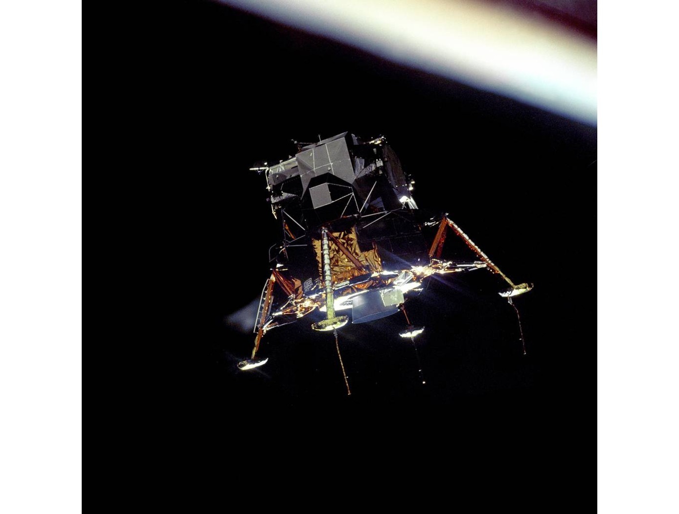
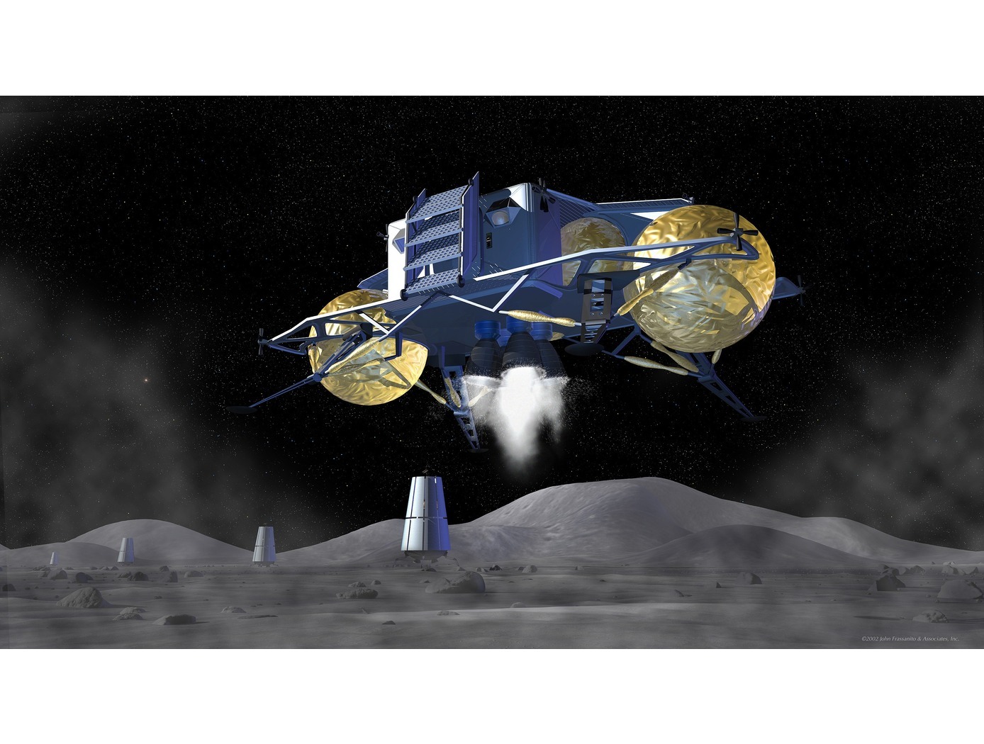
eVTOL UAS with Lunar Lander Trajectory
This NASA-developed eVTOL UAS is a purpose-built, electric, reusable aircraft with rotor/propeller thrust only, designed to fly trajectories with high similarity to those flown by lunar landers. The vehicle has the unique capability to transition into wing borne flight to simulate the cross-range, horizontal approaches of lunar landers. During transition to wing borne flight, the initial transition favors a traditional airplane configuration with the propellers in the front and smaller surfaces in the rear, allowing the vehicle to reach high speeds. However, after achieving wing borne flight, the vehicle can transition to wing borne flight in the opposite (canard) direction. During this mode of operation, the vehicle is controllable, and the propellers can be powered or unpowered.
This NASA invention also has the capability to decelerate rapidly during the descent phase (also to simulate lunar lander trajectories). Such rapid deceleration will be required to reduce vehicle velocity in order to turn propellers back on without stalling the blades or catching the propeller vortex. The UAS also has the option of using variable pitch blades which can contribute to the overall controllability of the aircraft and reduce the likelihood of stalling the blades during the deceleration phase.
In addition to testing EDL sensors and precision landing payloads, NASA’s innovative eVTOL UAS could be used in applications where fast, precise, and stealthy delivery of payloads to specific ground locations is required, including military applications. This concept of operations could entail deploying the UAS from a larger aircraft.
Manufacturing
Lunar Landing Pads
The jointly developed interlocking paver design consists of a molded solid material with tapered interlocking features that interface with features of an opposite gender in three orthogonal directions. This establishes a toleranced connection between the pavers that locks down six degrees of freedom.
More specifically, the system consists of two types of pavers: polygon and spacer pavers. Both are symmetrical about the longitudinal and transverse axes and are designed to interlock securely with one another in a checkerboard pattern. The polygon paver features an octagonal top level and a rectangular bottom level with protrusions and recessed notches. The spacer paver has an elongated center portion with isosceles trapezoid extensions on the top level and a rectangular bottom level with protrusions and notches. The interlocking design locks down six degrees of freedom, providing enhanced stability and preventing the flow of exhaust gases between the seams to mitigate erosion of the underlying regolith.
The pavers could be constructed leveraging in-situ resource utilization (ISRU). Lunar regolith has been identified as a potential construction material. Additionally, the pavers could be installed via robotic assembly, reducing the need for human labor in harsh environments.
Information Technology and Software
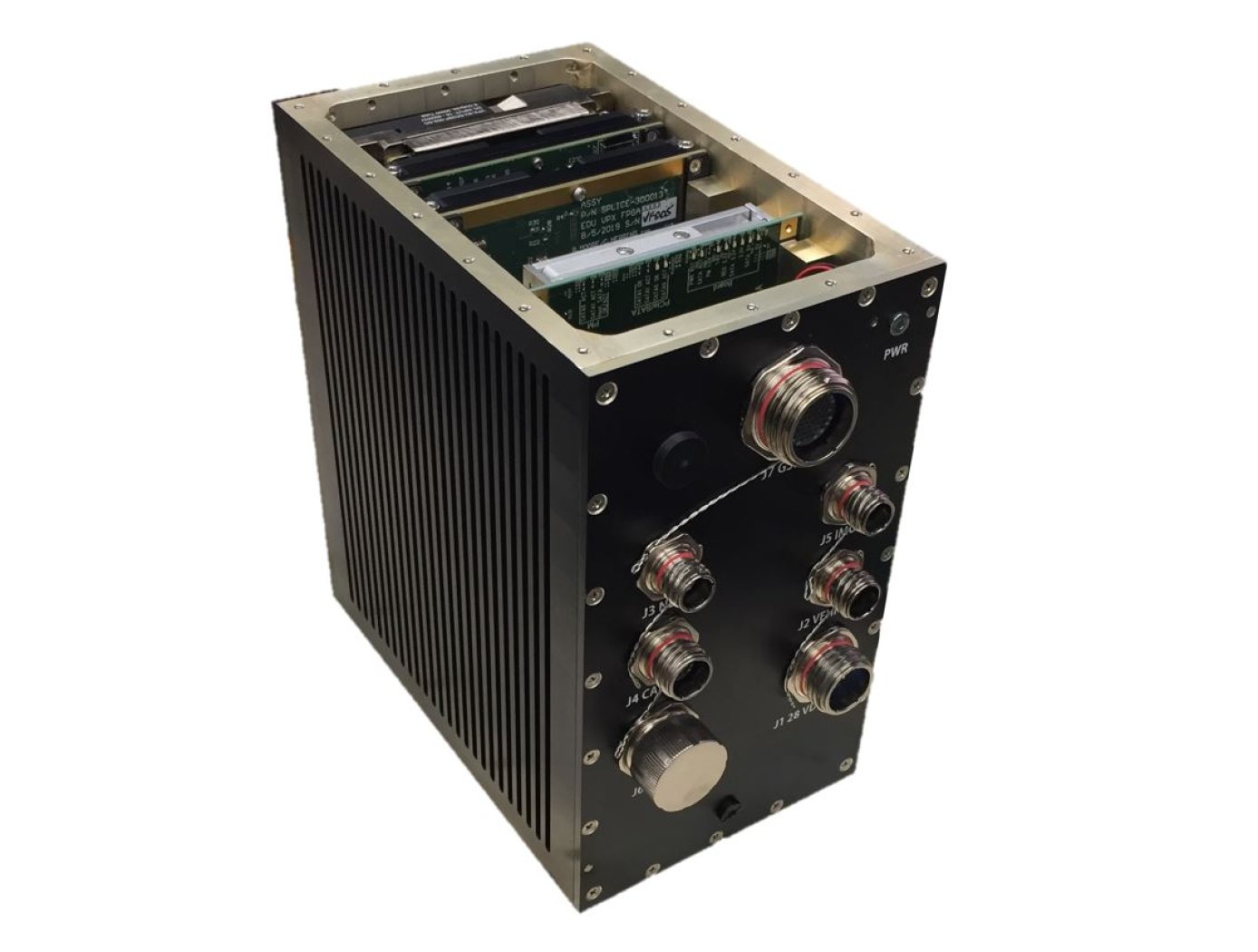
Unique Datapath Architecture Yields Real-Time Computing
The DLC platform is composed of three key components: a NASA-designed field programmable gate array (FPGA) board, a NASA-designed multiprocessor on-a-chip (MPSoC) board, and a proprietary datapath that links the boards to available inputs and outputs to enable high-bandwidth data collection and processing.
The inertial measurement unit (IMU), camera, Navigation Doppler Lidar (NDL), and Hazard Detection Lidar (HDL) navigation sensors (depicted in the diagram below) are connected to the DLC’s FPGA board. The datapath on this board consists of high-speed serial interfaces for each sensor, which accept the sensor data as input and converts the output to an AXI stream format. The sensor streams are multiplexed into an AXI stream which is then formatted for input to a XAUI high speed serial interface. This interface sends the data to the MPSoC Board, where it is converted back from the XAUI format to a combined AXI stream, and demultiplexed back into individual sensor AXI streams. These AXI streams are then inputted into respective DMA interfaces that provide an interface to the DDRAM on the MPSoC board. This architecture enables real-time high-bandwidth data collection and processing by preserving the MPSoC’s full ability.
This sensor datapath architecture may have other potential applications in aerospace and defense, transportation (e.g., autonomous driving), medical, research, and automation/control markets where it could serve as a key component in a high-performance computing platform and/or critical embedded system for integrating, processing, and analyzing large volumes of data in real-time.
Aerospace
Aerospace Vehicle Entry Flightpath Control
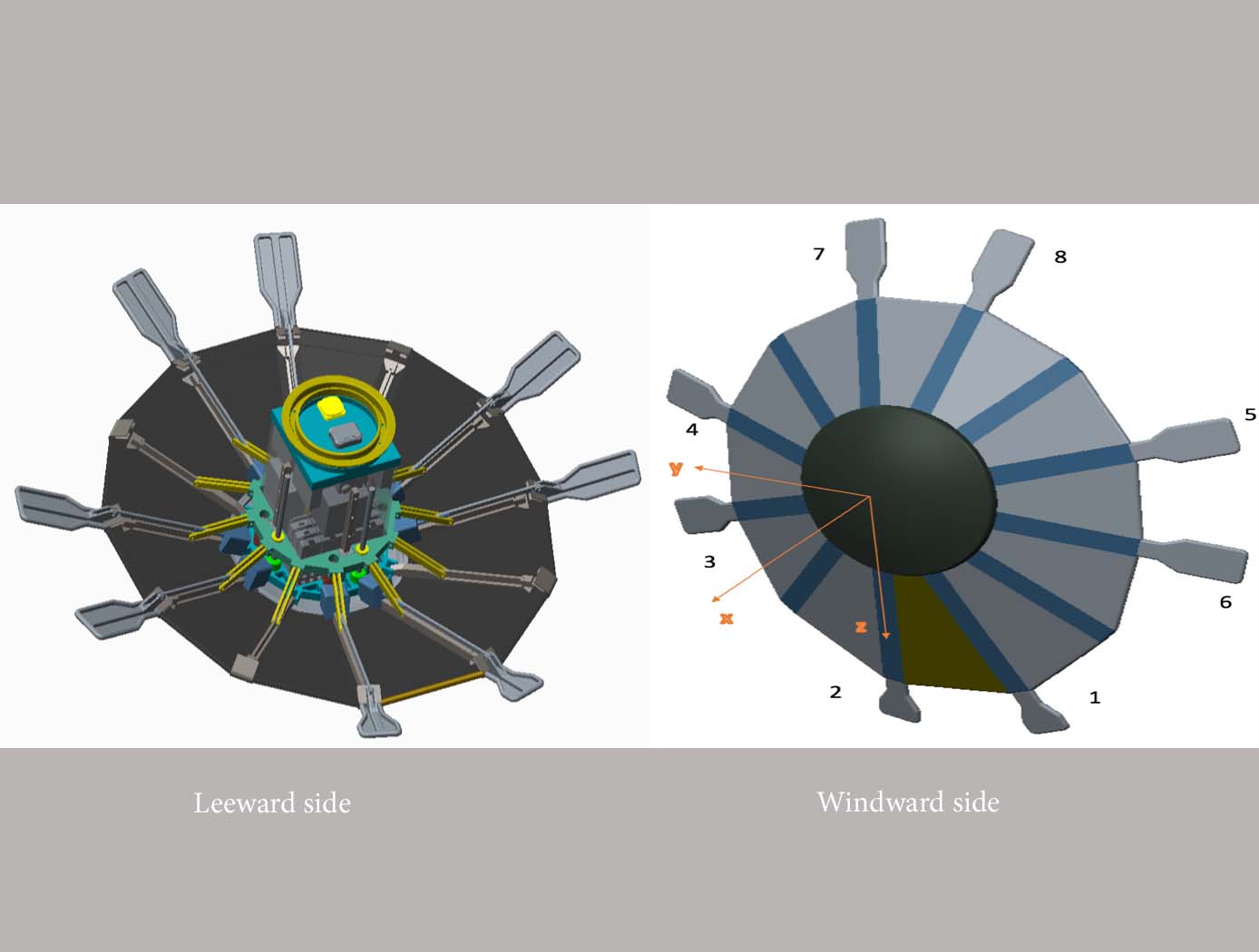
This novel flightpath control system exploits the dihedral effect to control the bank angle of the vehicle by modulating sideslip (Figure 1). Exploiting the dihedral effect, in combination with significant aerodynamic forces, enables faster bank accelerations than could be practically achieved through typical control strategies, enhancing vehicle maneuverability. This approach enables vehicle designs with fewer control actuators since roll-specific actuators are not required to regulate bank angle. The proposed control method has been studied with three actuator systems (figure below), Flaps Control System (FCS); Mass Movement Control System (MMCS); and Reaction Control System (RCS).
• FCS consists of a flap configuration with longitudinal flaps for independent pitch control, and lateral flaps generating yaw moments. The flaps are mounted to the shoulder of the vehicle’s deployable rib structure. Additionally, the flaps are commanded and controlled to rotate into or out of the flow. This creates changes in the vehicle’s aerodynamics to maneuver the vehicle without the use of thrusters.
• MMCS consists of moveable masses that are mounted to several ribs of the DEV heatshield, steering the vehicle by shifting the vehicle’s Center of Mass (CoM). Shifting the vehicle’s CoM adjusts the moment arms of the forces on the vehicle and changes the pitch and yaw moments to control the vehicle’s flightpath.
• RCS thrusters are mounted to four ribs of the open-back DEV heatshield structure to provide efficient bank angle control of the vehicle by changing the vehicle’s roll. Combining rib-mounted RCS thrusters with a Deployable Entry Vehicle (DEV) is expected to provide greater downmass capability than a rigid capsule sized for the same launch
Aerospace
Vision-based Approach and Landing System (VALS)
The novel Vision-based Approach and Landing System (VALS) provides Advanced Air Mobility (AAM) aircraft with an Alternative Position, Navigation, and Timing (APNT) solution for approach and landing without relying on GPS. VALS operates on multiple images obtained by the aircraft’s video camera as the aircraft performs its descent. In this system, a feature detection technique such as Hough circles and Harris corner detection is used to detect which portions of the image may have landmark features. These image areas are compared with a stored list of known landmarks to determine which features correspond to the known landmarks. The world coordinates of the best matched image landmarks are inputted into a Coplanar Pose from Orthography and Scaling with Iterations (COPOSIT) module to estimate the camera position relative to the landmark points, which yields an estimate of the position and orientation of the aircraft. The estimated aircraft position and orientation are fed into an extended Kalman filter to further refine the estimation of aircraft position, velocity, and orientation. Thus, the aircraft’s position, velocity, and orientation are determined without the use of GPS data or signals. Future work includes feeding the vision-based navigation data into the aircraft’s flight control system to facilitate aircraft landing.
Aerospace

Improved Hypersonic Aircraft Flight Control System
NASA’s MHD patch technology is composed of two electrodes positioned a prescribed distance apart recessed into angled channels on the surface of the TPS of an aircraft or spacecraft and an electromagnetic coil placed directly below the electrodes with the magnetic field protruding out of the surface. Note that the recessed/angled MHD patch described here is a special version of the original MHD patch described in LAR-TOPS-363. During hypersonic flight, the conductive ionizing atmospheric flow over the surface permits current to flow between the two electrodes. This current is harnessed to power the electromagnet which in turn generates strong Lorentz forces that augment lift and drag forces for guidance, navigation, and control of the craft. Alternatively, the current can be used to charge a battery. Changing the size of the MHD patch (e.g., the length or distance between the electrodes), the strength of the electromagnet, or the direction of the magnetic field enables tuning of generated forces for a given craft design. Multiple MHD patches can be leveraged on a single craft.
In-silico evaluation of the non-recessed, non-angled MHD patch technology on select aeroshell designs for mock entry into planetary atmospheres has been performed. A single 1m<sup>2</sup> MHD patch exerts forces up to 200 kN under simulated Neptune atmosphere entry that can be used to control a craft.
Aerospace
3D Lidar for Autonomous Landing Site Selection
Aerial planetary exploration spacecraft require lightweight, compact, and low power sensing systems to enable successful landing operations. The Ocellus 3D lidar meets those criteria as well as being able to withstand harsh planetary environments. Further, the new tool is based on space-qualified components and lidar technology previously developed at NASA Goddard (i.e., the Kodiak 3D lidar) as shown in the figure below.
The Ocellus 3D lidar quickly scans a near infrared laser across a planetary surface, receives that signal, and translates it into a 3D point cloud. Using a laser source, fast scanning MEMS (micro-electromechanical system)-based mirrors, and NASA-developed processing electronics, the 3D point clouds are created and converted into elevations and images onboard the craft. At ~2 km altitudes, Ocellus acts as an altimeter and at altitudes below 200 m the tool produces images and terrain maps. The produced high resolution (centimeter-scale) elevations are used by the spacecraft to assess safe landing sites.
The Ocellus 3D lidar is applicable to planetary and lunar exploration by unmanned or crewed aerial vehicles and may be adapted for assisting in-space servicing, assembly, and manufacturing operations. Beyond exploratory space missions, the new compact 3D lidar may be used for aerial navigation in the defense or commercial space sectors. The Ocellus 3D lidar is available for patent licensing.
Aerospace

Aerodynamic Framework for Parachute Deployment from Aerial Vehicle
For rapid parachute deployment simulation, the framework and methodology provided by the simulation database uses parametrized aerodynamic data for a variety of environmental conditions, air taxi design parameters, and landing system designs. The database also includes a compilation of drag coefficients, thrust and lift forces, and further relevant aerodynamic parameters utilized in the simulated flight of a proposed air taxi. The database and framework can be constructed using simulated data that accounts for oscillatory breathing of parachutes. The methodology can further employ an overset grid of body-fitted meshes to accurately capture deployment of an internally-stored parachute, as well as descent of the air taxi and deployed parachute.
The systems and methods of the disclosed technology can be utilized with existing CFD solvers in a plug-and-play manner, such that the framework can be integrated to directly improve the performance of these solvers and the machines on which they are installed. The framework itself can employ parallelization to enable distributed solution of intensive CFD simulations to build a robust database of simulated data. Further, as up to 90% of computational time is spent in the calculation of aerodynamic parameters for use in coupled trajectory equations, the framework can significantly reduce the computational costs and design time for safe landing systems for air taxis. These reductions can lead to lower costs for design processes, while enabling rapid design and testing prior to physical prototyping.
Aerospace
Active Turbulence Suppression System for Electric Vertical Take-Off and Landing (eVTOL) vehicles
The Active Turbulence Suppression (ATS) system for electric Vertical Take-Off and Landing (eVTOL) vehicles employ existing lifting propellers to dampen instabilities during flight, such as Dutch-roll oscillations and other gust-induced oscillations. When a roll angle of an eVTOL aircraft has deviated or is about to deviate from a current stable aircraft state to an undesirable, unstable, and oscillating aircraft state, the ATS system queries a turbulence suppression database that stores a set of propeller speed profiles for mitigation a deviation of a given roll angle for a particular aircraft with specified propellers. Using this data, the eVTOL flight controller adjusts the speed of the propellers for a certain duration of time, according to the propeller speed profiles for mitigating the deviation. In models of aircraft with adjustable propeller angles, the database includes blade angle profiles for mitigating the effects of turbulent conditions. Timing and rate of propeller activation can be pre-computed using higher order computational modeling performed with NASA’s super computing resources. Because the data is pre-computed, the use of the ATS system onboard does not require significant computing resources to implement on eVTOL vehicles. The technology, a mechanism by which existing eVTOL propellers are leveraged to suppress gust-induced oscillations enables a safe and comfortable passenger experience at low-cost and without added hardware.
Aerospace

Wind-Optimal Cruise Airspeed Mode for Flight Management Systems (FMS)
The novel approach for optimizing airspeed for both actual and predicted wind conditions in electric Vertical Takeoff and Landing (eVTOL) aircraft with Distributed Electric Propulsion (DEP) systems includes the process of creating a lookup table for wind‐optimal airspeed as a function of wind magnitude, considering the direction of the wind relative to the cruise segment, considering the cruise altitude for an aircraft type, and incorporating the wind-optimal airspeed lookup table in the performance database for real‐time access by the Flight Management Systems (FMS) to predict wind-optimal airspeed at waypoints of the flight plan. The target wind‐optimal airspeed is updated in real-time throughout the cruise portion of a flight.
In a test of the wind-optimal airspeed targeting technique using a multi-rotor aircraft model, results obtained show benefits of flying at the wind‐optimal cruise airspeed compared to the best‐range airspeed. In headwind conditions, energy consumption was reduced by up to 7.5%, and flight duration was reduced by up to 28%. Under uncertain wind magnitudes, flying at wind-optimal airspeed offered lower variability and higher predictability in energy consumption than flying at best‐range airspeed.

