ShuttleSCAN 3-D
instrumentation
ShuttleSCAN 3-D (TOP2-128)
Patent Only, No Software Available For License.
Overview
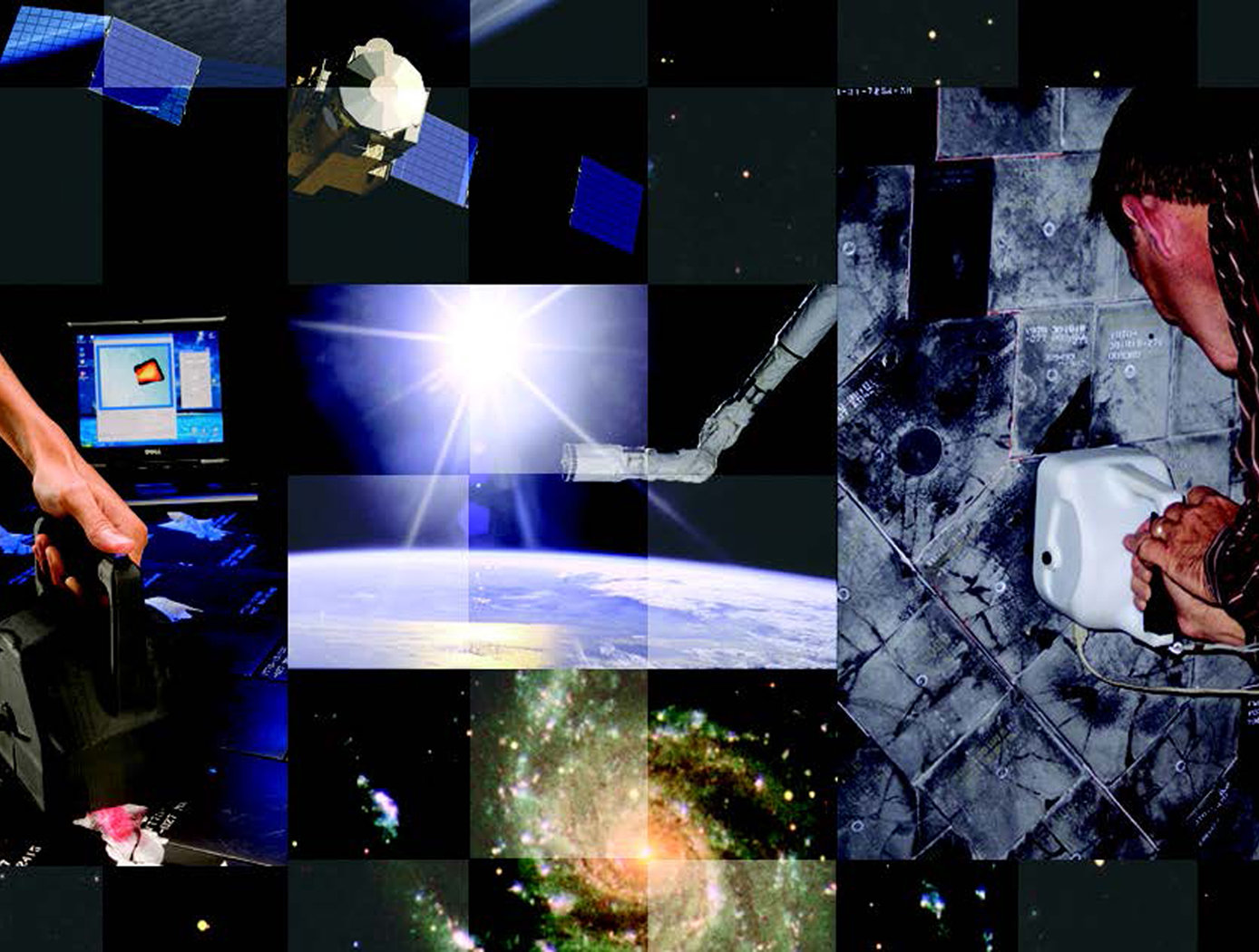
NASA Ames Research Center offers for license its patented ShuttleSCAN 3-D surface scanning and profiling technology. Originally developed for critical, real-time inspection of damage to the thermal protection tiles of the Space Shuttle, this advanced system can be used for a wide range of commercial applications from product quality control to autonomous navigation. Powered by the onboard Surface Profiling and Characterization Engine (SPACE) processor, ShuttleSCAN provides real-time analysis of surfaces ranging from the small (such as circuit boards) to the large (such as panels or roads).
The Technology
How It Works
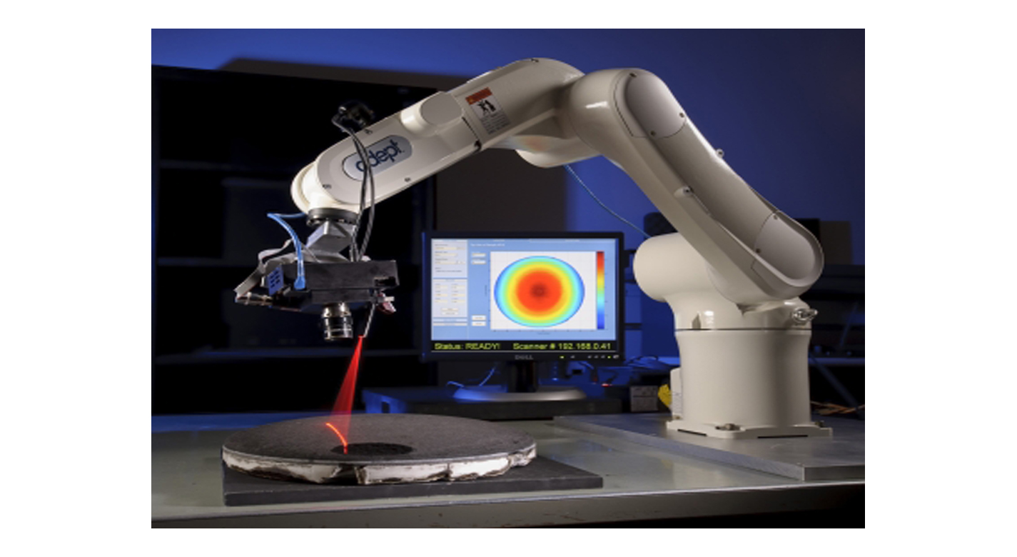
The scanners operation is based on the principle of Laser Triagulation. The ShuttleSCAN contains an imaging sensor; two lasers mounted on opposite sides of the imaging sensor; and a customized, on-board processor for processing the data from the imaging sensor. The lasers are oriented at a given angle and surface height based on the size of objects being examined. For inspecting small details, such as defects in space shuttle tiles, a scanner is positioned close to the surface. This creates a small field of view but with very high resolution. For scanning larger objects, such as use in a robotic vision application, a scanner can be positioned several feet above the surface. This increases the field of view but results in slightly lower resolution. The laser projects a line on the surface, directly below the imaging sensor. For a perfectly flat surface, this projected line will be straight. As the ShuttleSCAN head moves over the surface, defects or irregularities above and below the surface will cause the line to deviate from perfectly straight. The SPACE processors proprietary algorithms interpret these deviations in real time and build a representation of the defect that is then transmitted to an attached PC for triangulation and 3-D display or printing. Real-time volume calculation of the defect is a capability unique to the ShuttleSCAN system.
Why It Is Better
The benefits of the ShuttleSCAN 3-D system are very unique in the industry. No other 3-D scanner can offer the combination of speed, resolution, size, power efficiency, and versatility. In addition, ShuttleSCAN can be used as a wireless instrument, unencumbered by cables. Traditional scanning systems make a tradeoff between resolution and speed. ShuttleSCANs onboard SPACE processor eliminates this tradeoff. The system scans at speeds greater than 600,000 points per second, with a resolution smaller than .001". Results of the scan are available in real time, whereas conventional systems scan over the surface, analyze the scanned data, and display the results long after the scan is complete.


Benefits
- High-speed 3-D scans: Creates more than 600,000 3-D points/secondamong the highest available
- Fast results: Provides results in real time from the integrated SPACE processor
- Versatility: Scans areas from square centimeters to square meters
- High resolution: Detects details smaller than .001 inch (with smallest field of view architecture)
- Small footprint: The small 7.25 x 5.5 x 5.4-inch size and lightweight package (2.9 lbs) is also power efficient (over 1000 scans from the re-chargeable lithium battery)
- Wireless: Offers 802.11G wireless or Gigabit Ethernet wired connectivity
Applications
- Inspection of aircraft and spacecraft fuselage surfaces, wings, etc.
- Autonomous navigation by mobile robots (e.g., Mars Rover)
- Inspection of pipelines (oil, natural gas, water) for corrosion-related defects
- Optical 3-D scanning of printed circuit boards for inspection and positioning
- Scanning reusable metal hardware sealing surfaces to detect flaws that would impact sealing ability
- Scanning industrial machined parts for dimensional accuracy
- Road surface profiling
|
Tags:
|
Similar Results

Robust Sensors Detect Material Ablation and Temperature Changes
Glenn's breakthrough technology introduces batch-fabricated, miniature sensors embedded and distributed over a large surface area of a material or product during the manufacturing process. The sensors can be utilized for test instrumentation or as an integrated in-situ monitoring system. This integrated manufacturing approach preserves the structural and mechanical system integrity by eliminating the antiquated plug-in approach, invasive machining, manual insertion, and gluing processes currently required to implant sensors into a material. The sensor ladder network of resistors and capacitors breaks down as result of the thermo-physical effects caused by temperature, shock, radiation, corrosion, or other reactions, causing a change in the electrical properties. A processor interprets these changes in the electrical properties and generates a high-resolution, large-area surface profile. The profile demonstrates the amount or rate of material deterioration and temperature change, and is used to optimize geometric structural design, develop materials, predict performance, and make decisions. These sensors play an important role as industries work to realize material performance and product design. This type of monitoring is ideal for infrastructures, nuclear enclosures, or any system susceptible to surface deterioration.

Robotic Inspection System for Fluid Infrastructures
The Robotic Inspection System improves the inspection of deep sea structures such as offshore storage cells/tanks, pipelines, and other subsea exploration applications. Generally, oil platforms are comprised of pipelines and/or subsea storage cells. These storage cells not only provide a stable base for the platform, they provide intermediate storage and separation capability for oil. Surveying these structures to examine the contents is often required when the platforms are being decommissioned. The Robotic Inspection System provides a device and method for imaging the inside of the cells, which includes hardware and software components. The device is able to move through interconnected pipes, even making 90 degree turns with minimal power. The Robotic Inspection System is able to display 3-dimentional range data from 2-dimensional information. This inspection method and device could significantly reduce the cost of decommissioning cells. The device has the capability to map interior volume, interrogate integrity of cell fill lines, display real-time video and sonar, and with future development possibly sample sediment or oil.
Multidimensional Damage Detection System
The Damage Detection System consists of layered composite material made up of two-dimensional thin film damage detection layers separated by thicker, nondetection layers, coupled with a detection system. The damage detection layers within the composite material are thin films with a conductive grid or striped pattern. The conductive pattern can be applied on a variety of substrates using several different application methods. The number of detection layers in the composite material can be tailored depending on the level of damage detection detail needed for a particular application. When damage occurs to any detection layer, a change in the electrical properties of that layer is detected and reported. Multiple damages can be detected simultaneously, providing real-time detail on the depth and location of the damage.
The truly unique feature of the System is its flexibility. It can be designed to gather as much (or as little) information as needed for a particular application using wireless communication. Individual detection layers can be turned on or off as necessary, and algorithms can be modified to optimize performance. The damage detection system can be used to generate both diagnostic and prognostic information related to the health of layered composite structures, which will be essential if such systems are utilized to protect human life and/or critical equipment and material.
.jpg)
Interim, In Situ Additive Manufacturing Inspection
The in situ inspection technology for additive manufacturing combines different types of cameras strategically placed around the part to monitor its properties during construction. The IR cameras collect accurate temperature data to validate thermal math models, while the visual cameras obtain highly detailed data at the exact location of the laser to build accurate, as-built geometric models. Furthermore, certain adopted techniques (e.g., single to grouped pixels comparison to avoid bad/biased pixels) reduce false positive readings.
NASA has developed and tested prototypes in both laser-sintered plastic and metal processes. The technology detected errors due to stray powder sparking and material layer lifts. Furthermore, the technology has the potential to detect anomalies in the property profile that are caused by errors due to stress, power density issues, incomplete melting, voids, incomplete fill, and layer lift-up. Three-dimensional models of the printed parts were reconstructed using only the collected data, which demonstrates the success and potential of the technology to provide a deeper understanding of the laser-metal interactions. By monitoring the print, layer by layer, in real-time, users can pause the process and make corrections to the build as needed, reducing material, energy, and time wasted in nonconforming parts.

In-situ Characterization and Inspection of Additive Manufacturing Deposits using Transient Infrared Thermography
Additive manufacturing or 3-D printing is a rapidly growing field where solid, objects can be produced layer by layer. This technology will have a significant impact in many areas including industrial manufacturing, medical, architecture, aerospace, and automotive. The advantages of additive manufacturing are reduction in material costs due to near net shape part builds, minimal machining required, computer assisted builds for rapid prototyping, and mass production capability. Traditional thermal nondestructive evaluation (NDE) techniques typically use a stationary heat source such as flash or quartz lamp heating to induce a temperature rise. The defects such as cracks, delamination damage, or voids block the heat flow and therefore cause a change in the transient heat flow response. There are drawbacks to these methods.


